Process for producing plastic parts

a plastic and processing technology, applied in the direction of adhesives, etc., can solve the problems of inability to deform, high labor intensity, and substantial loss of stability or rigidity, and achieve the effect of saving time, cost and production spa

Inactive Publication Date: 2006-02-02
EIPPER KONRAD +1
View PDF7 Cites 4 Cited by
  • Summary
  • Abstract
  • Description
  • Claims
  • Application Information

AI Technical Summary

Benefits of technology

[0031] It is particularly advantageous when the three dimensional deformation and the separation of the components by separating, for ex...

Problems solved by technology

This is very labor intensive, time consuming, expensive and, in the case of certain plastics such as for example duroplastics, not possible by deforming.
Further, in the case of sha...

Method used


Image

  • Process for producing plastic parts
  • Process for producing plastic parts

Examples


Embodiment Construction

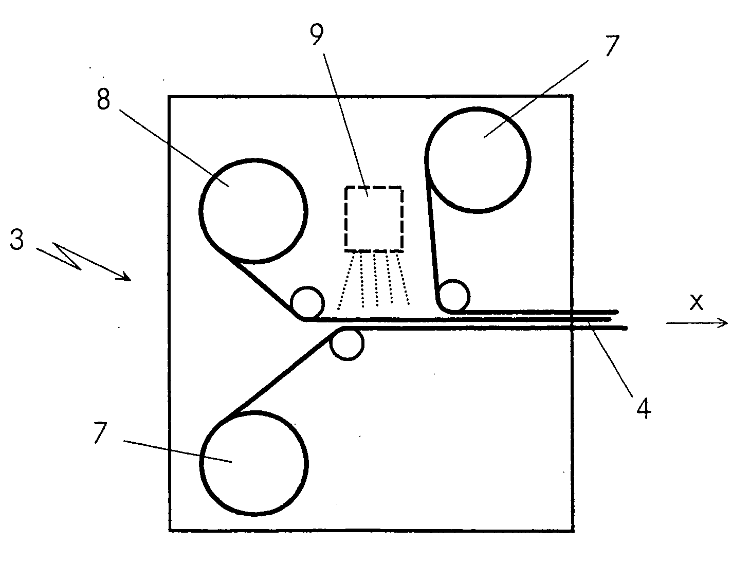
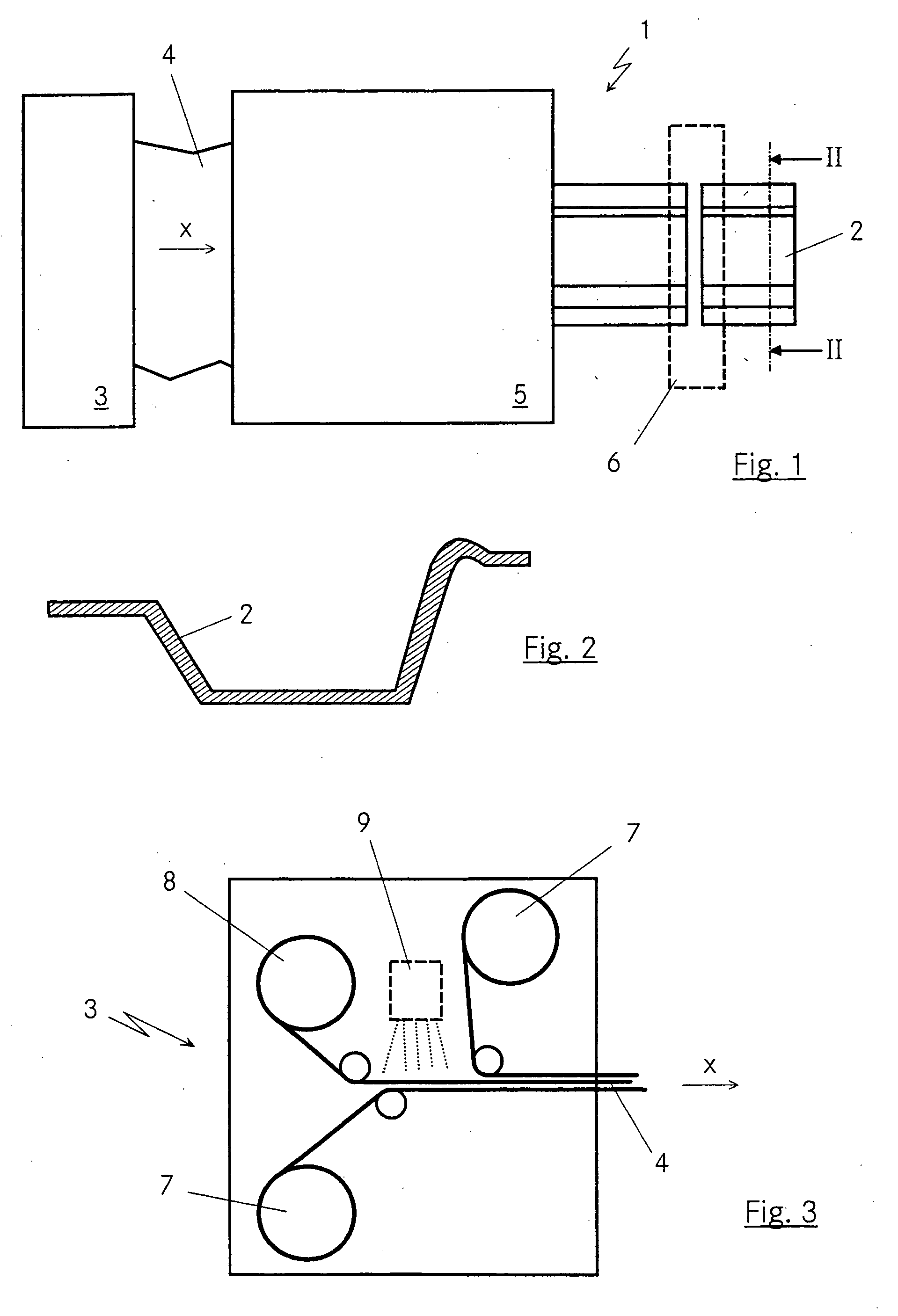
[0037] In FIG. 1 an exemplary conceivable device 1 for production of components 2 is illustrated. This device 1 is comprised essentially of a device 3 for providing plastic material 4. Both the device 3 as well as the plastic material 4 could be variously designed or constituted, as will be described later.

[0038] Leaving the device 3, the plastic material 4 then reaches a roller profiling 5. The plastic material 4 is deformed there into the component 2 by various rollers, which are changeably controllable in their position and speed for example by CNC. By a roller profiling 5 of this type, which is frequently referred to as roller deforming, various two dimensional or—by a bending in the direction of advance x of the plastic material—three dimensional component shapes can be realized. FIG. 2 shows for example one possible cross section through a conceivable two dimensional shape of such a component 4.

[0039] The actual manufacture of the component 2 from the plastic material 4 occu...


PUM

PropertyMeasurementUnit
Speedaaaaaaaaaa
Metallic bondaaaaaaaaaa
Plasticityaaaaaaaaaa

Abstract

A process for production of components of a plastic material, in particular fiber-reinforced plastic material. The component is produced starting with a device for providing plastic material to a continuous manufacturing process involving roller profiling of heated plastic material. The plastic material is assembled in the device for providing of plastic material of several different stock or semi-finished parts. At least one of the stock or semi-finished parts is made of a metallic material, in particular sheet metal.

Description

BACKGROUND OF THE INVENTION [0001] 1. Field of the Invention [0002] The invention concerns a process for producing parts made of plastic, in particular a fiber reinforced plastic. [0003] 2. Related Art of the Invention [0004] It is well known to use rollers in processing of plastics for production of planar and flat plates, bands or sheets. Examples thereof can be found in DE 101 12 296 A1 and DE 40 33 661 A1 as well as DE 41 31 394 A1, in particular for the production of so-called sandwiched sheets of multiple material layers. These sheets however represent only preforms, which later can or, as the case may be, must be further processed separately from their original manufacture. This is very labor intensive, time consuming, expensive and, in the case of certain plastics such as for example duroplastics, not possible by deforming. The processing necessary, for example, shape cutting, is associated with trimming or waste, which in particular in the case of fiber-reinforced plastics ...

Claims


Application Information

Patent Timeline
IPC IPC(8): B29C65/00
CPCB29C43/22Y10T156/1002B29C70/545B29C70/504
Inventor EIPPER, KONRADSCHMD, KLAUS-ERIK
Owner EIPPER KONRAD
Why Eureka
Try Eureka