
Series/parallel turbochargers and switchable high/low pressure EGR for internal combustion engines

a turbocharger and internal combustion engine technology, applied in the direction of machines/engines, mechanical equipment, electric control, etc., can solve the problems of additional warm-up time, turbo delay or lag, less desirable transient response, and small turbos with limited air handling capacity for higher engine speeds. , to achieve the effect of generating more boost, reducing inertia, and sufficient air handling capacity

Inactive Publication Date: 2006-02-02
FORD GLOBAL TECH LLC
View PDF15 Cites 103 Cited by
  • Summary
  • Abstract
  • Description
  • Claims
  • Application Information

AI Technical Summary

Benefits of technology

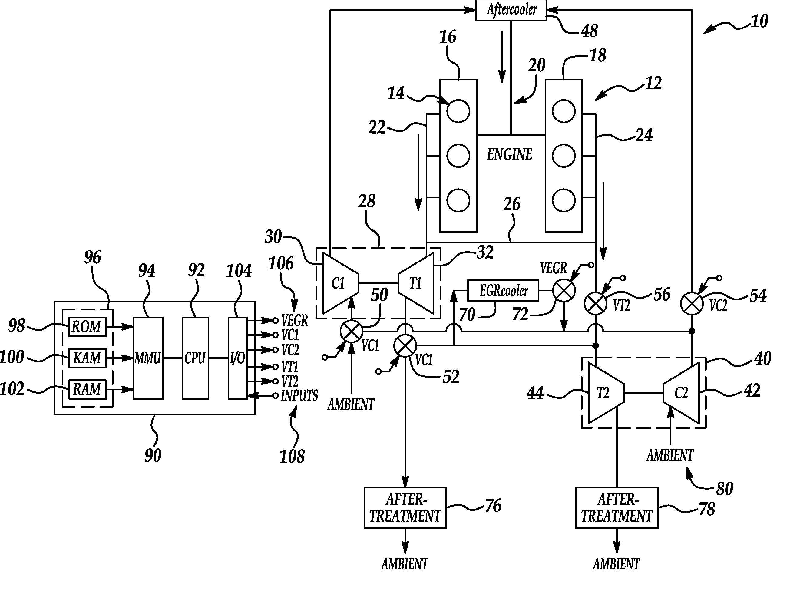
[0012] The present invention provides a number of advantages. For example, the selectable turbocharger configuration according to the present invention provides a two stage series configuration to generate more boost for improved vehicle launch compared to a sequential parallel configuration that only uses one stage at low engine speeds, while providing a parallel configuration to provide sufficient air handling capacity at higher engine speeds using smaller turbochargers with lower inertia to improve turbocharger efficiency and transient response across the entire operating range. The sequential operation of twin turbochargers in a series configuration followed by a parallel configuration according to the present invention provides improved performance in terms of airflow, turbo wheel speed, and air pressure build up during transients relative to previous approaches.
[0013] The switchable or floating exhaust gas recirculation according to the present invention may selectively source EGR downstream of the first turbine to provide more exhaust gas to power the first turbine with termination upstream of the compressor to improve surge margin at lower speeds while sourcing EGR upstream of the first turbine with termination downstream of the compressor at higher speeds to avoid choking at full load.
[0014] Operation of the twin turbochargers in a series configuration according to the present invention may reduce the time required for emission control or exhaust after treatment devices to reach desired operating temperatures by directing all exhaust through one or more designated devices. Optional exhaust switching according to the present invention may be used to control exhaust flow and temperatures of primary and secondary after treatment devices to conduct sequential after treatment regeneration and extend the life of the after treatment system.

Problems solved by technology

However, a smaller turbo has limited air handling capacity for higher engine speeds.
A turbo with sufficient airflow capacity for higher engine speeds generally has larger mass and inertia leading to noticeable turbo delay or lag and a less desirable transient response.
EGR handling and control strategies typically require similar compromises.
However, the higher airflows and thermal inertia associated with single or twin turbochargers may often require additional warm-up time before the emission control devices reach desired operating temperatures.
However, to accommodate the higher mass flow capacity at higher engine speeds requires a larger rotor with corresponding inertia resulting in a slower transient response.
However, this configuration includes some turbo lag or transient delay for speed-up or spooling of the secondary VGT, which is idled or not used at low engine speeds.
To handle airflow at higher engine speeds in this configuration, the required sizing and associated inertia of the secondary turbocharger compromises transient performance of the primary turbocharger leading to undesirable turbo lag or delay.

Method used


Image

  • Series/parallel turbochargers and switchable high/low pressure EGR for internal combustion engines
  • Series/parallel turbochargers and switchable high/low pressure EGR for internal combustion engines
  • Series/parallel turbochargers and switchable high/low pressure EGR for internal combustion engines

Examples


Embodiment Construction

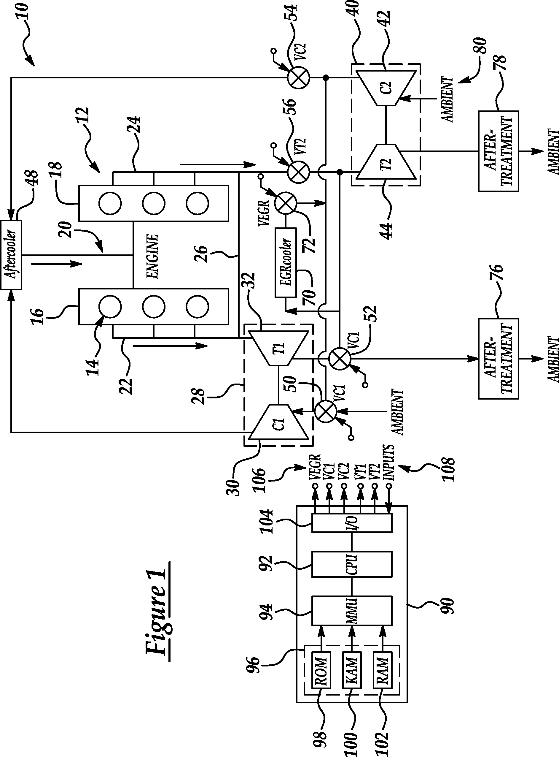
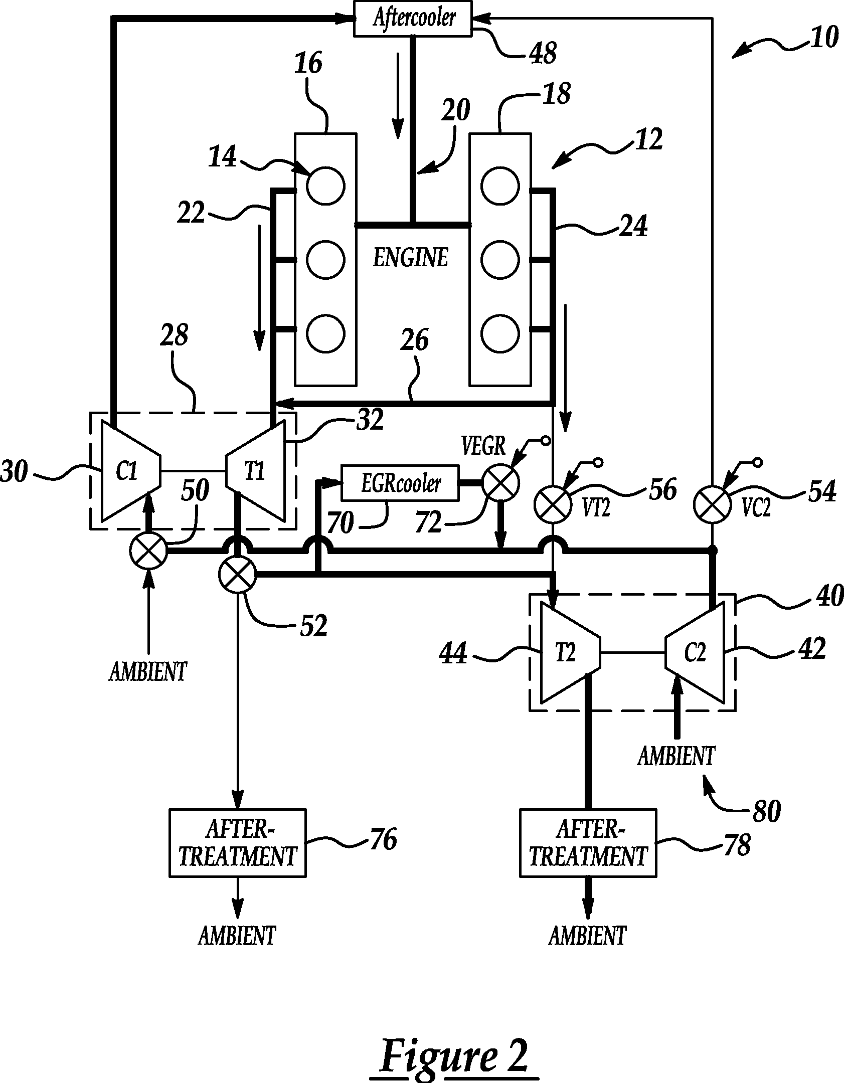
[0023] A block diagram illustrating a system or method for turbocharged an internal combustion engine according to one embodiment of the present invention is shown in FIG. 1. As illustrated in FIG. 1, system 10 includes an internal combustion engine 12 having a plurality of cylinders 14. In the example illustrated in FIG. 1, cylinders 14 are arranged in two banks 16 and 18. However, the present invention is independent of the particular cylinder arrangement and may also be applied to in-line configurations, for example. Similarly, while a six-cylinder engine is illustrated, the present invention may be applied to internal combustion engines having any number of cylinders. Preferably, the present invention is applied to turbocharged internal combustion engines utilizing compression ignition technology, such as diesel engines. However, those of ordinary skill in the art will recognize that the present invention is generally independent of the particular type of engine.

[0024] Intake m...


PUM


Abstract

Systems and methods for turbocharging an internal combustion engine include operating two turbochargers in a series configuration for a first operating region and a parallel configuration for a second operating region. Systems and methods for controlling exhaust gas recirculation (EGR) in a turbocharged internal combustion engine provide low pressure EGR upstream of a compressor inlet for a first operating region and high pressure EGR downstream of a compressor outlet for a second operating range to further improve turbocharger operating margin and overall efficiency.

Description

BACKGROUND OF INVENTION [0001] 1. Field of the Invention [0002] The present invention relates to systems and methods for turbocharging and providing exhaust gas recirculation for internal combustion engines. [0003] 2. Background Art [0004] Sizing a turbocharger for a particular engine application traditionally requires compromises to achieve a fast transient response from idle with a desired boost when launching a vehicle, especially when using exhaust gas recirculation (EGR), while providing sufficient air handling capacity at high engine speeds. Generally, a fast transient response requires a smaller turbo with lower inertia. However, a smaller turbo has limited air handling capacity for higher engine speeds. A turbo with sufficient airflow capacity for higher engine speeds generally has larger mass and inertia leading to noticeable turbo delay or lag and a less desirable transient response. [0005] EGR handling and control strategies typically require similar compromises. At light...

Claims


Application Information

Patent Timeline
Patent Type & Authority Applications(United States)
IPC IPC(8): F02B33/44
CPCF02B29/0406F02B37/013F02B37/18F02D9/02F02D9/04F02D23/00F02B37/004F02D41/0065F02M25/0711F02M25/0727Y02T10/144Y02T10/47F02D41/0007F02M26/08F02M26/23Y02T10/12Y02T10/40
Inventor SUN, HAROLDRUONA, WILLIAMBAKER, RICHARDKING, EDWARD
Owner FORD GLOBAL TECH LLC
Learn More