
Removal of particle contamination on a patterned silicon/silicon dioxide using dense fluid/chemical formulations

a technology of patterned silicon and silicon dioxide, which is applied in the preparation of detergent mixture compositions, fluorine-based surface-active compounds, detergent compounding agents, etc., can solve the problems of not all surfaces to be cleaned are smooth, and complicating the cleaning process

Inactive Publication Date: 2006-01-26
ADVANCED TECH MATERIALS INC
View PDF34 Cites 35 Cited by
  • Summary
  • Abstract
  • Description
  • Claims
  • Application Information

AI Technical Summary

Benefits of technology

"The present invention is about a new cleaning composition that can remove particles from microelectronic device substrates. The composition includes dense carbon dioxide, alcohol, fluoride, anionic surfactant, non-ionic surfactant, and optionally, a hydroxyl additive. The cleaning composition can effectively remove particle contamination from microelectronic devices, resulting in improved device performance and reliability. The invention also includes a kit for making the cleaning composition and a method of making microelectronic devices using the cleaning composition."

Problems solved by technology

All of the methods developed to date have associated deficiencies.
More generally, the problems attendant the removal of contaminant particles from microelectronic device substrates include the fact that surface contamination may be organic and / or inorganic in character, thereby complicating the cleaning process from the perspective of selecting compatible cleaning agents.
In addition, not all surfaces to be cleaned are smooth and may possess varying degrees of roughness due to previous etching and / or deposition processes, thereby complicating the cleaning procedure.
Accordingly, flow characteristics, chemistry and physical aspects are all involved, and complicate the removal of particulate contamination.

Method used


Image

  • Removal of particle contamination on a patterned silicon/silicon dioxide using dense fluid/chemical formulations
  • Removal of particle contamination on a patterned silicon/silicon dioxide using dense fluid/chemical formulations
  • Removal of particle contamination on a patterned silicon/silicon dioxide using dense fluid/chemical formulations

Examples


example 1

[0077] The sample wafers examined in this study included silicon nitride particles residing on a patterned silicon dioxide layer and silicon layer. The samples were first processed using pure SCCO2 at 50° C. and 4400 psi, and although the velocity of the flowrate (10 mL / min) removed some of the particles, it was ineffective at completely removing all of the contaminate particles.

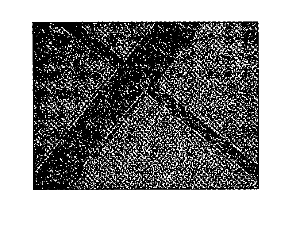
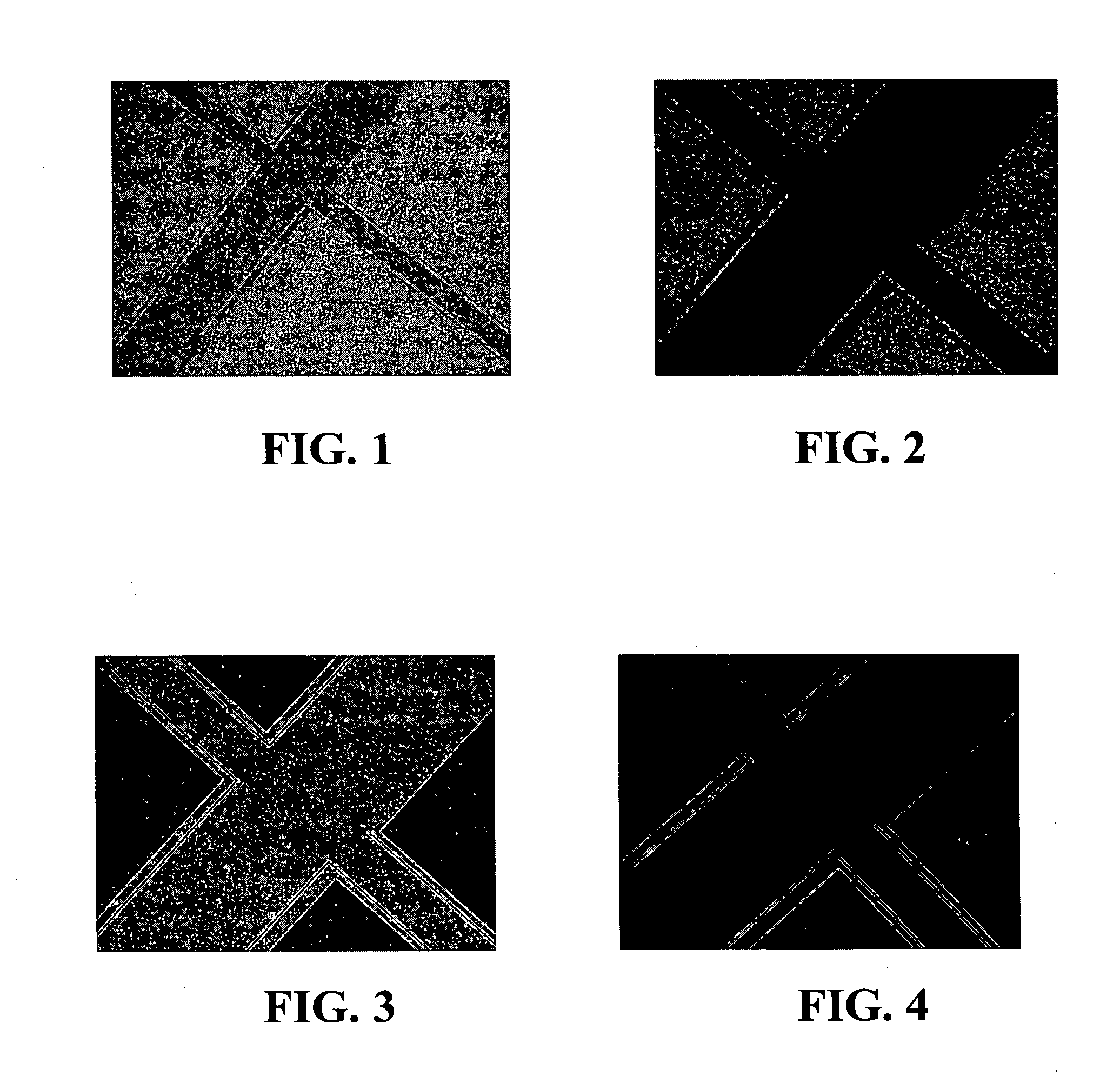
[0078]FIG. 1 is an optical microscope photograph of this wafer comprising a patterned silicon dioxide layer and silicon layer, showing contaminant particles of SiN thereon, subsequent to cleaning thereof with SCCO2 / methanol solution.

[0079] Various chemical additives / surfactants then were added to the SCCO2 / methanol solution and their particle removal efficiency was examined.

[0080]FIG. 2 shows the optical image of the wafer cleaned with a SCCO2 / methanol / boric acid / NH4F solution at 50° C. and clearly shows that the SiN particles are removed from the SiO2 surface, however, this cleaning solution was not effe...

example 2

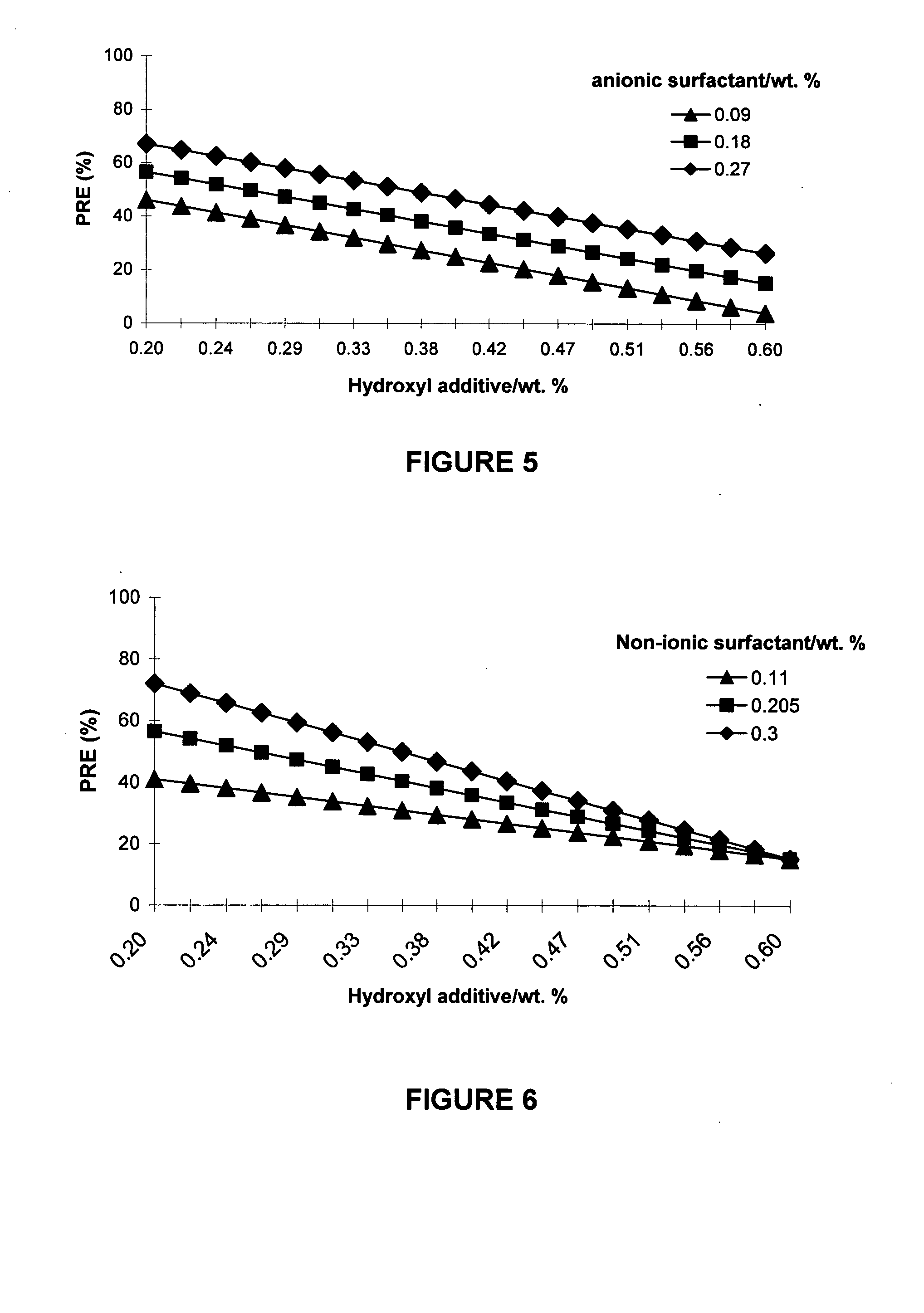
[0085] The sample wafers examined in this study included silicon or silicon oxide wafers having silicon nitride particle matter thereon. The processing conditions included temperature of 70° C., pressure around 3000 psi and a process time in the range of 2 to 30 minutes, preferably in the range of 5 to 10 minutes. The process flow used may be either a static soak or a dynamic flow. The cleaning composition included SCCO2, about 5 wt. % to about 15 wt. % methanol, boric acid as the hydroxyl additive, about 0.8 wt. % ammonium fluoride as the etchant, non-ionic surfactant and anionic surfactant.

[0086]FIG. 5 illustrates the particle removal efficiency (PRE) for the removal of silicon nitride particles from a silicon surface using a cleaning composition including 0.205 wt. % non-ionic surfactant and varying concentrations of hydroxyl additive and anionic surfactant. It can be seen that both the anionic surfactant and the hydroxyl additive have an effect on the PRE, whereby the lower the...

example 3

[0092] Using the optimized cleaning composition of Example 2, patterned silicon / silicon oxide wafers having silicon nitride particle matter thereon were cleaned to determine the effects of temperature and pressure on the PRE, keeping all other variables constant. The cleaning composition included SCCO2, about 5 wt. % to about 15 wt. % methanol, a low concentration of boric acid as the hydroxyl additive, about 0.8 wt. % ammonium fluoride as the etchant, a high concentration of non-ionic surfactant and a high concentration of anionic surfactant.

[0093]FIG. 11 illustrates the particle removal efficiency (PRE) for the removal of silicon nitride particles from the patterned silicon / silicon oxide surface, as well as the etch rate of the silicon / silicon oxide surface, using the SCCO2 cleaning composition at a constant pressure of 2800 psi. It can be seen that as the temperature of the composition is increased, both the PRE and the etch rate of the silicon and silicon oxide surfaces increas...


PUM

PropertyMeasurementUnit
pressureaaaaaaaaaa
temperaturesaaaaaaaaaa
pressureaaaaaaaaaa

Abstract

A cleaning composition for cleaning particulate contamination from small dimensions on microelectronic device substrates. The cleaning composition contains dense CO2 (preferably supercritical CO2 (SCCO2)), alcohol, fluoride source, anionic surfactant source, non-ionic surfactant source, and optionally, hydroxyl additive. Such cleaning composition overcomes the intrinsic deficiency of SCCO2 as a cleaning reagent, viz., the non-polar character of SCCO2 and its associated inability to solubilize species such as inorganic salts and polar organic compounds that are present in particulate contamination on wafer substrates and that must be removed from the microelectronic device substrate for efficient cleaning. The cleaning composition enables damage-free, residue-free cleaning of substrates having particulate contamination on Si / SiO2 substrates.

Description

CROSS REFERENCE TO RELATED APPLICATIONS [0001] This is a continuation-in-part of U.S. patent application Ser. No. 10 / 284,861 for “Removal of Particle Contamination on Patterned Silicon / Silicon Dioxide Using Supercritical Carbon Dioxide / Chemical Formulations” filed on Oct. 31, 2002 in the name of Michael Korzenski et al.FIELD OF THE INVENTION [0002] The present invention relates to dense carbon dioxide-based compositions useful in microelectronic device manufacturing for the removal of particle contamination from patterned silicon / silicon dioxide substrates having such particle contamination thereon, and to methods of using such compositions for removal of particle contamination from microelectronic device substrates. DESCRIPTION OF THE RELATED ART [0003] In the field of microelectronic device manufacturing, various methods are in use for cleaning of wafers to remove particle contamination. These methods include ultrasonics, high pressure jet scrubbing, excimer laser ablation, and ca...

Claims


Application Information

Patent Timeline
Patent Type & Authority Applications(United States)
IPC IPC(8): C11D7/32
CPCB08B7/0021C11D1/004C11D1/83C11D3/042C11D3/046H01L21/02101C11D3/2034C11D3/24C11D11/0047H01L21/02063C11D3/201C11D2111/22C11D7/32
Inventor KORZENSKI, MICHAEL B.XU, CHONGYINGBAUM, THOMAS H.
Owner ADVANCED TECH MATERIALS INC
Learn More