
Storage system

a storage system and circuit board technology, applied in the field of storage systems, can solve the problems of unavoidable shutdown (operation stop) of the os for firmware updating and service interruption due to reboot of the computer system, and the inability to update the firmware on the circuit board with services to clients

Active Publication Date: 2006-01-19
RAKUTEN GRP INC
View PDF12 Cites 97 Cited by
  • Summary
  • Abstract
  • Description
  • Claims
  • Application Information

AI Technical Summary

Benefits of technology

The present invention provides a technique for updating firmware in a storage system while continuing to provide services to clients. This is achieved by using a circuit board with a plurality of circuit boards and a control unit to carry out firmware updates and service processing. The technical effect of this invention is that it allows for continuous firmware updates while maintaining service provision to clients.

Problems solved by technology

Conventionally, in the storage system, it has been unable to update the firmware on the circuit board with services to clients continued.
That is, from the viewpoint of mechanism concerning the firmware, for a single computer, shut-down (operation stop) of OS for firmware updating and service interruption due to reboot of the computer system has been unavoidable.

Method used


Image

  • Storage system
  • Storage system
  • Storage system

Examples


embodiment 1

[0100] Now the description will be made on the storage system in embodiment 1 according to the present invention. FIG. 4 illustrates a functional block configuration of the whole computer system including the storage system in embodiment 1 according to the present invention. In the present figure, in particular, portions involved in updating the firmware held by circuit boards composing the control unit 100 are primarily illustrated.

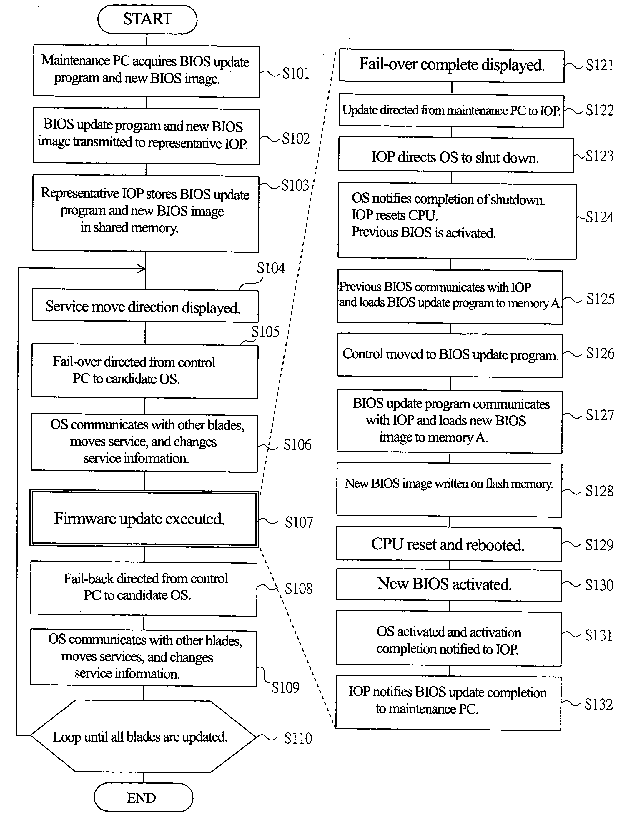
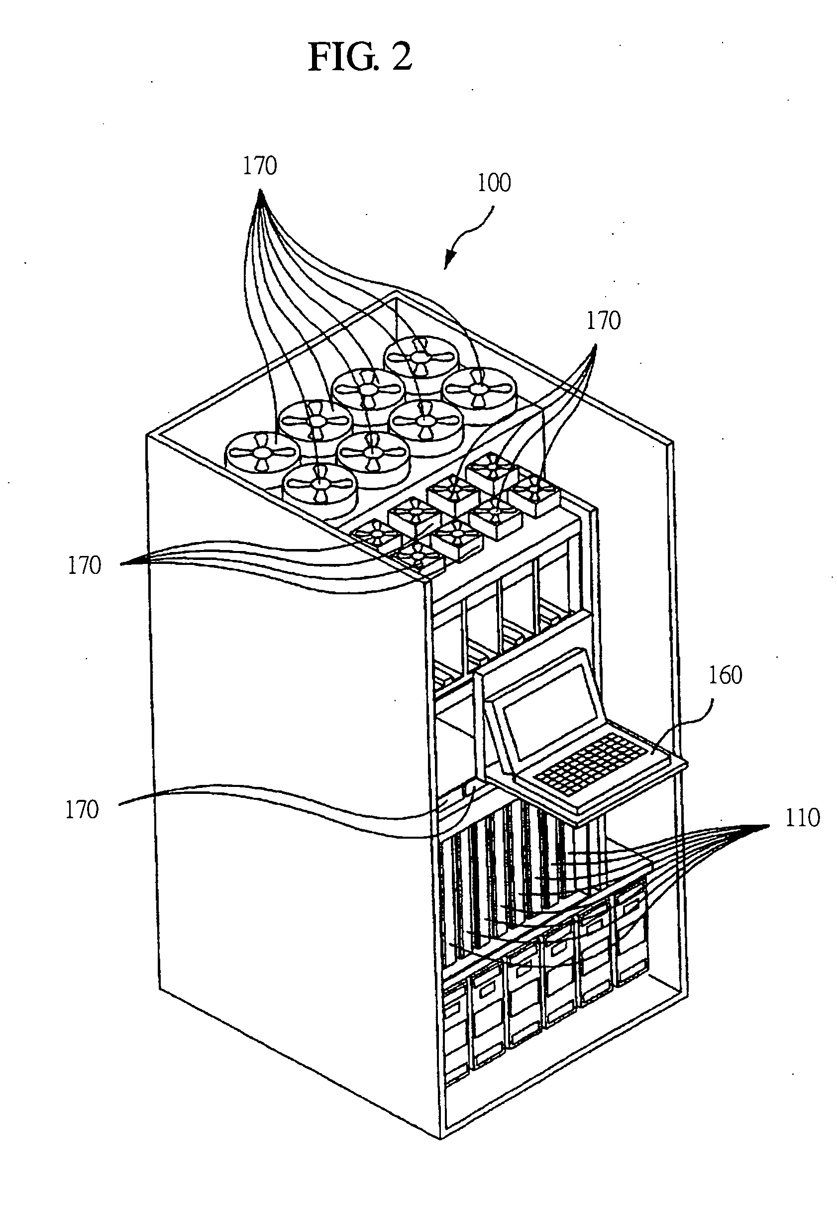
[0101] In the firmware update method (to be called the first firmware update method) at the storage system of embodiment 1, the firmware is updated by the use of the control terminal 160 with special emphasis placed on the control at IOP in the circuit boards that compose the control unit 100. The circuit boards form a cluster with the circuit board targeted for the update of the firmware included in the control unit 100. By executing properly fail-over for taking on services between circuit boards in the cluster, the firmware of each circuit board is u...

embodiment 2

[0183] Next discussion will be made as follows on the storage system in embodiment 2 according to the present invention. FIG. 14 indicates a functional block configuration of the whole computer system including the storage system in embodiment 2 according to the present invention. In particular, the present figure illustrates primarily the sections involved in updating the firmware held by circuit boards which compose the control unit 100. The hardware configuration of the storage system according to embodiment 2 is same as that of embodiment 1, but processing implemented from software differs. In embodiment 2, same as embodiment 1, clusters are formed and control information and OS condition information 27 for services are stored and controlled in memory.

[0184] In the firmware updating method in the storage system of embodiment 2 (hereinafter called the second firmware updating method), firmware is updated with special emphasis on the control by OS 21 operating on CPU 11 of blade ...


PUM


Abstract

A technique that can update the firmware with services for clients continued on a circuit board that comprises a control unit of a storage system is provided. A plurality of blade that comprise control unit have previous BIOS on flash memory. Clusters are formed including the blade which is subject to firmware update. At the time of updating the firmware, for the update candidate substrate, the processing unit including processing to move the service provided by OS of blade to be subject to firmware update processing to OS of other blade in the cluster as well as firmware update processing for updating previous BIOS of blade which no longer provides services by the use of the BIOS update program and new BIOS image.

Description

CROSS-REFERENCE TO RELATED APPLICATION [0001] The present application claims priority from Japanese Patent Application No. JP 2004-208105 filed on Jul. 15, 2004, the content of which is hereby incorporated by reference into this application. TECHNICAL FIELD OF THE INVENTION [0002] The present invention relates to a storage system (also called a disk-array unit) for carrying out the control to store data in a storage unit, and in particular, to a technique for updating firmware including BIOS (Basic Input Output System) of a circuit board in the storage system. [0003] In the storage system that carries out control for storing the data in a storage unit, in particular, the storage device used in companies and others, it is required to operate 24 hours a day every day in 365 days without stopping. Updating of firmware (version upgrading, etc.) in such a storage system, rebooting (restart) is involved as with other computer systems, and services to clients must be temporarily interrupte...

Claims


Application Information

Patent Timeline
Patent Type & Authority Applications(United States)
IPC IPC(8): G06F9/44
CPCG06F8/665G06F8/67G06F8/656G06F8/654
Inventor TAKATA, YUTAKAKOBAYASHI, NAOTAKAHASHIMOTO, TAKESHIHASHIMOTO, AKIYOSHINAKAYAMA, SHINICHI
Owner RAKUTEN GRP INC
Learn More