
Forged roller

Active Publication Date: 2006-01-19
THE NAT MASCH CO
View PDF1 Cites 10 Cited by
  • Summary
  • Abstract
  • Description
  • Claims
  • Application Information

AI Technical Summary

Benefits of technology

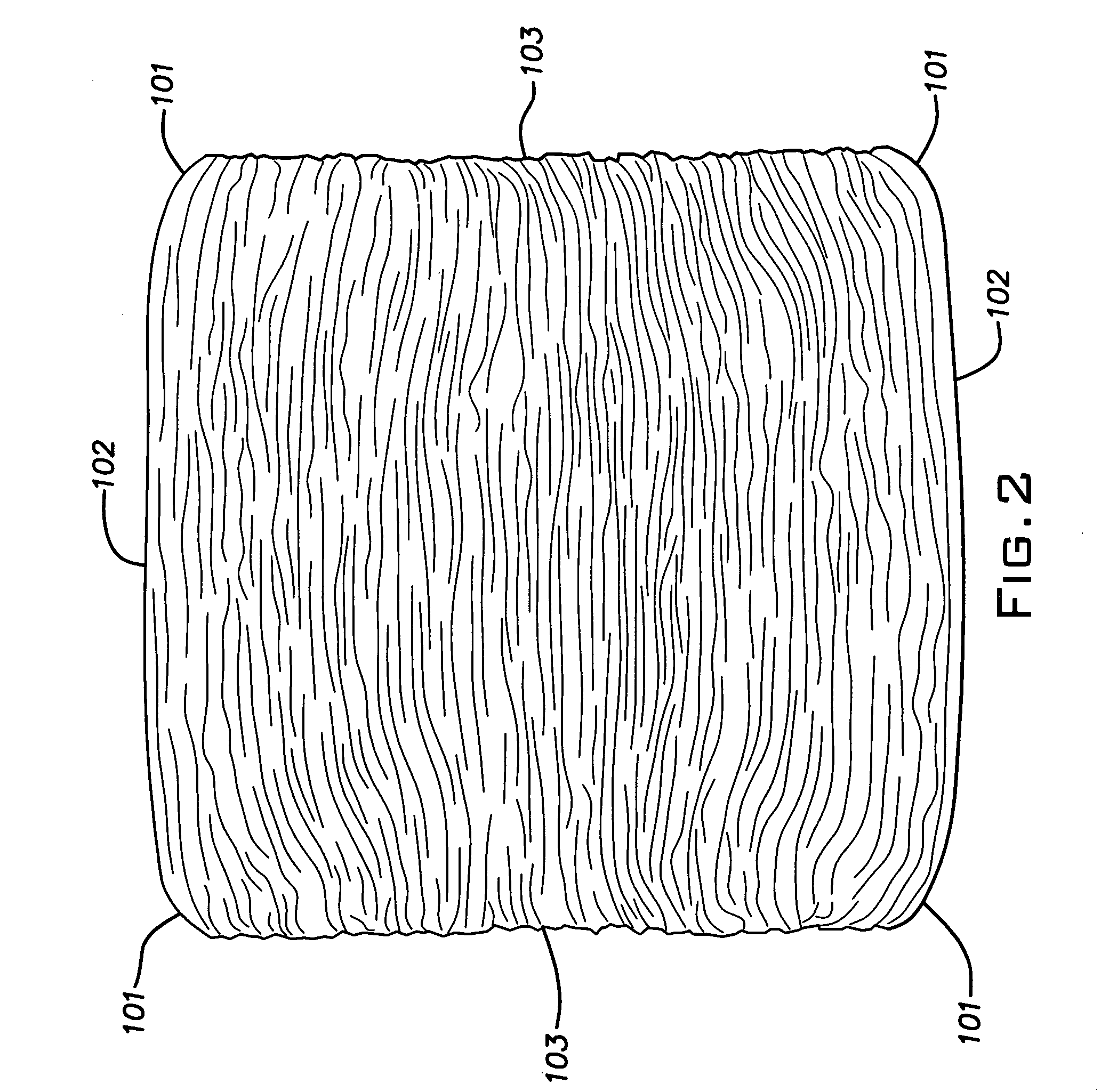
[0003] The invention involves a cold-formed metal roller blank, that is relatively close to the net shape of a finish ground roller thereby greatly reducing machining or grinding costs and that has an improved grain structure which avoids premature bearing failure. The improved cold-formed part results from tooling elements that closely shape a part without flash and with a grain structure that follows the contours of the end edges of the roller and is axially uninterrupted thereby avoiding irregularities in the finished machined product.
[0004] The process involves multistage forming steps and unique tooling capable of producing accurate shapes at each station without the need or risk of flash. The tooling is configured to work a blank that is relatively small in diameter compared to prior art practice, into a part of substantially increased diameter. This technique assures that the material of the sheared end faces of the original blank are essentially excluded from the formed radiused corners between the zone of the rolling surface of the roller and the end faces of the roller.
[0005] The roller blank or workpiece is simultaneously formed at each end, at each station. The annular radiused corners at the ends of the workpiece are progressively accurately formed by filling the corresponding tool and die cavity areas at successive workstations without creating or risking flash at separation planes between the tool and die cavity parts. This flashless forming is accomplished by confining and shaping the mid-length of the blank with a floating die ring that eliminates the effects of friction at the sides of the workpiece which otherwise would inhibit material flow into the cavity corners and promote or require unwanted flash. At the last station, the workpiece is precision formed by closing the tool and die with a positive stop so that the tool geometry determines the final part shape independently of machine variables.

Problems solved by technology

Typically, grinding operations may involve several steps because the cold-formed part has significant flash and / or excess material as a result of the limitations and characteristics of traditional methods and tooling used in the cold-forming art.
Grinding processes are expensive and significantly add to the cost of the finished roller.

Method used


Image

  • Forged roller
  • Forged roller
  • Forged roller

Examples


Embodiment Construction

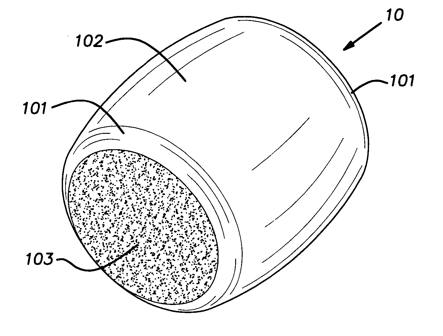
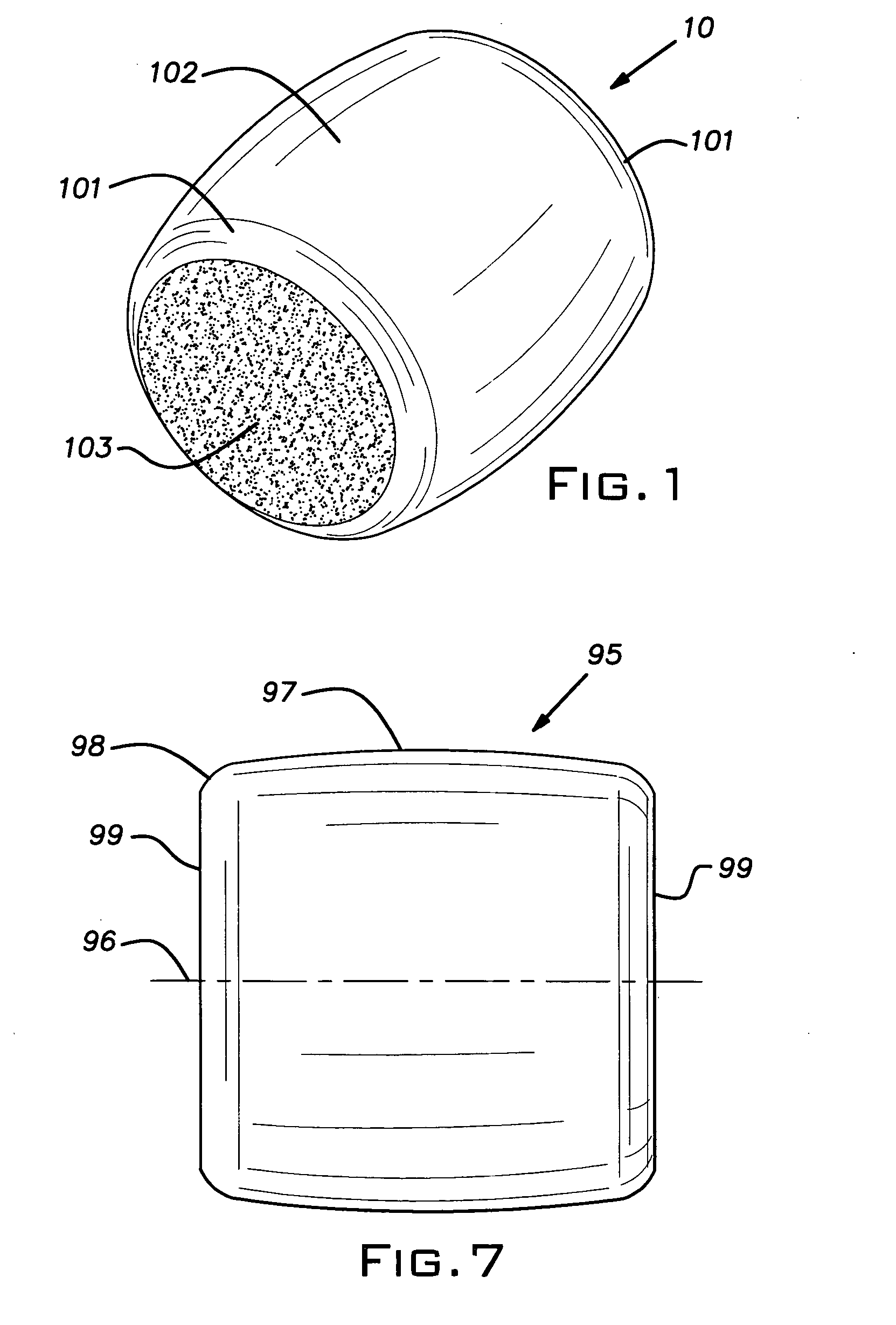
[0014]FIG. 1 illustrates an example of a cold-formed roller blank 10 made in accordance with the present invention. The roller blank is of the barrel type, but it will be appreciated that certain principles of the invention are applicable to other roller styles including cylindrical and tapered rollers. The roller blank 10 made by the processes and tools disclosed hereinbelow can be produced to dimensional tolerances that are reduced to about 1 / 10 of that which is presently commercially accepted for subsequent finishing, typically by grinding after heat treatment. The roller blank 10 after heat treating and grinding is typically used with multiple identical pieces in anti-friction bearing assemblies as known in the art.

[0015] The roller 10 is formed in a multistation progressive cold-forming machine 11 illustrated in FIG. 3 and of a type generally known in the industry. The forging machine 11 is depicted in a plan view of the tooling area in FIG. 3. The machine 11 includes a quill ...


PUM

PropertyMeasurementUnit
Temperatureaaaaaaaaaa
Lengthaaaaaaaaaa
Diameteraaaaaaaaaa

Abstract

A machine, method and tooling to precision cold-form roller blanks for anti-friction bearings. The machine is a multistage progressive former using floating die cavities to enable simultaneous shaping of the ends of the roller with high accuracy and without flash. The tools and staged forming create an improved roller with an advantageous grain pattern and devoid of structural defects previously attributable to the presence of sheared end face material in the radiused corners of the blank and flash at its mid-section.

Description

BACKGROUND OF THE INVENTION [0001] The invention relates to the manufacture of cold-formed rollers and, in particular, to a process, machine and tooling that affords improvements in roller quality and reduction in manufacturing costs. PRIOR ART [0002] Rollers used in anti-friction bearings are commonly initially made in cold-forming machines. Traditionally, the cold-formed pieces are subsequently machined by grinding processes to achieve a desired precision shape and finish. Typically, grinding operations may involve several steps because the cold-formed part has significant flash and / or excess material as a result of the limitations and characteristics of traditional methods and tooling used in the cold-forming art. Grinding processes are expensive and significantly add to the cost of the finished roller. SUMMARY OF THE INVENTION [0003] The invention involves a cold-formed metal roller blank, that is relatively close to the net shape of a finish ground roller thereby greatly reduci...

Claims


Application Information

Patent Timeline
IPC IPC(8): F16C33/34
CPCB21J5/02B21J9/022Y10T29/49693B21K1/02F16C33/36B21J13/03
Inventor KRINTZLINE, DONALD E.BORDNER, MARK W.
Owner THE NAT MASCH CO
Learn More