
Tire mold

Inactive Publication Date: 2006-01-12
TOYO TIRE & RUBBER CO LTD
View PDF4 Cites 25 Cited by
  • Summary
  • Abstract
  • Description
  • Claims
  • Application Information

AI Technical Summary

Benefits of technology

[0009] It is an object of the present invention to restrict protrusion of rubber when performing molding and to mold a tire of superior uniformity.
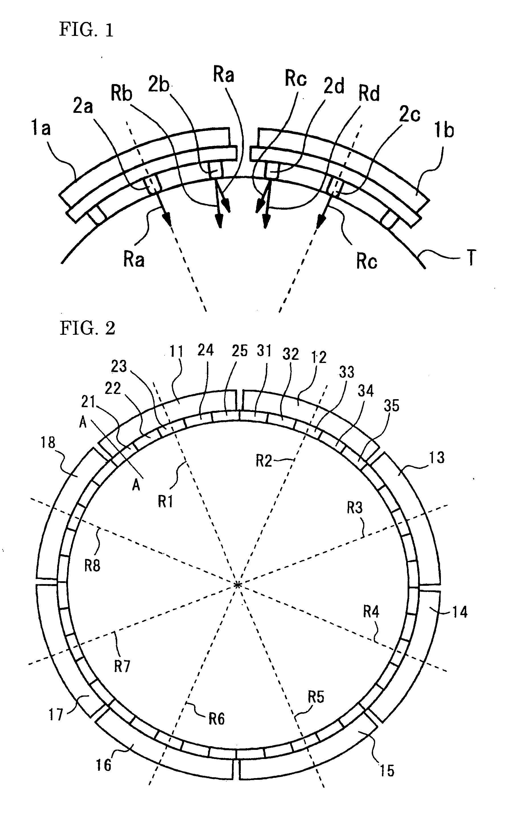
[0013] The mold according to the present invention is arranged in that segments partitioned in the tire circumferential direction comprise a plurality of pieces that are partitioned in the tire circumferential direction, wherein only one piece of each segment is fixed while all other pieces are movable in the tire circumferential direction. Accordingly, while respective pieces are apart from each other in a condition in which the mold is open, pieces of adjoining segments abut each other in the course of reducing the inner radius of the mold cavity, and the mold is closed while narrowing the clearance between the pieces. All pieces including the pieces at end portions of the each segment substantially move in radial directions of the tire. As a result, even if the pieces comprise projecting streaks for forming grooves, no movements of the rubber caused through the projecting streaks as discussed above will occur so that it is possible to restrict protrusion of rubber when performing molding and to mold tires exhibiting superior uniformity.
[0014] Due to the fact that one piece of the each segment is fixed, the entire piece is prevented from rotating in the tire circumferential direction, and no shifts in molded tread patterns (design shifts) will be caused. While the piece to be fixed may be any piece located at any position of the each segment, it is desirable to define it to be a piece at a central portion of the each segment at which the distance of movement in the tire circumferential direction is small or a piece at an end portion of the each segment that exhibits dropout preventing effects.
[0015] Since clearances between the pieces that are formed until the mold is completely closed will function as vent holes, it will not be necessary to arrange vent holes at the mold so that it is possible to restrict occurrence of so-called bears.
[0021] As discussed above, the pneumatic tire molded by using the mold according to the present invention is free of protrusions of rubber and is superior in uniformity.
[0022] In the tire mold of the present invention, the mold is closed while the clearance between a plurality of pieces partitioned in the tire circumferential direction is narrowed, and the pieces substantially move in radial directions of the tire. As a result, no movement of rubber caused through projecting streaks formed at the pieces will occur so that it is possible to restrict protrusion of rubber when performing molding and to mold a tire of superior uniformity.

Problems solved by technology

Moreover, the movement of the rubber will lead to an uneven thickness of the tread part which might cause degradations in tire performances.
In such a case, the outer radius of the tire became large through the molding so that a framework of tires was grown in size which would lead to degradations in tire durability.

Method used


Image

  • Tire mold
  • Tire mold
  • Tire mold

Examples


Embodiment Construction

[0028] An embodiment of a tire mold according to the present invention will now be explained on the basis of the drawings. FIG. 2 illustrates a condition in which the mold according to the present invention is closed. The mold for molding a tire tread is partitioned into eight segments 11 to 18, and is movable in a tire radial direction. For instance, the segment 11 is movable in a tire radial direction R1.

[0029] Each segment comprises a plurality of pieces further partitioned in a tire circumferential direction. For instance, the segment 11 comprises pieces 21 to 25, and the segment 12 comprises pieces 31 to 35. The piece 21 and others comprise projecting streaks (not shown) for forming grooves on a tread surface.

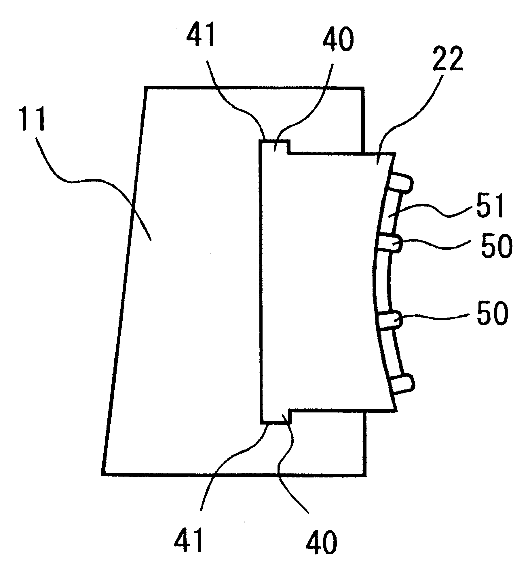
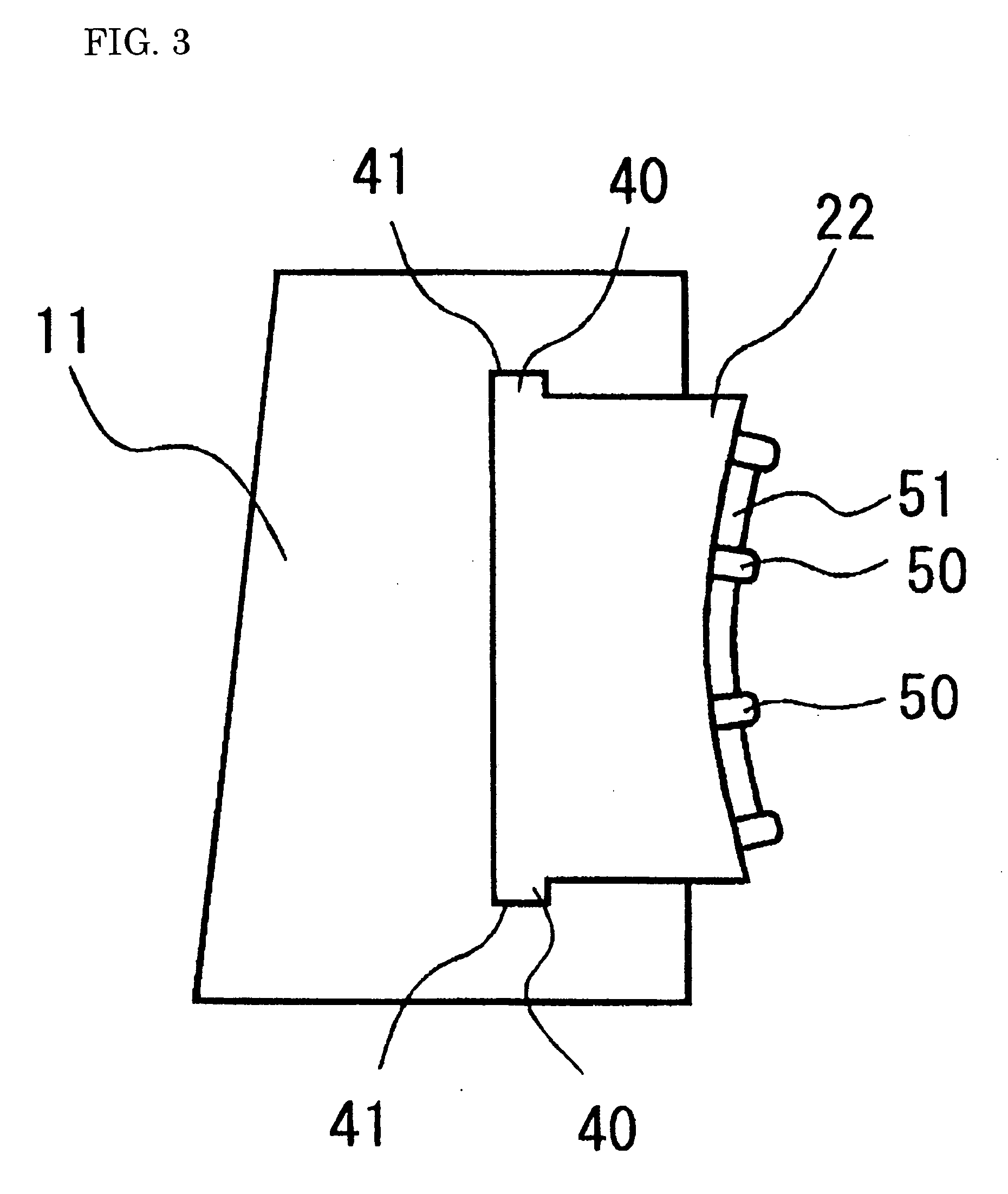
[0030]FIG. 3 is a sectional view along line A-A in FIG. 2. In the drawings, the piece 21 comprises a projection (or projecting streak) 40 and engages with a groove 41 engraved in the segment 11 along the tire circumferential direction. Accordingly, the piece 21 and other...


PUM

PropertyMeasurementUnit
Lengthaaaaaaaaaa
Lengthaaaaaaaaaa
Repulsive forceaaaaaaaaaa

Abstract

It is a subject to restrict protrusion of rubber when performing molding and to mold tires of superior uniformity; and for this purpose, the tire mold in which a mold for molding a tire tread is comprised of segments partitioned in a tire circumferential direction is arranged in that segments 11, 12 comprise a plurality of pieces 21 to 25 and 31 to 35 partitioned in the tire circumferential direction, with only one 23, 33 of the pieces of the each segment 11, 12 being fixed while all other pieces 21, 22, 24, 25 and so on are movable in the tire circumferential direction.

Description

BACKGROUND OF THE INVENTION [0001] 1. Field of the Invention [0002] The present invention relates to a tire mold in which parts for molding a tread are partitioned into a plurality of segments, and particularly to a technique of restricting protrusion of rubber into clearances between adjoining segments and of molding tires exhibiting superior uniformity. [0003] 2. Description of the Prior Art [0004] In performing molding of pneumatic tires, sector partitioned mold in which parts for molding treads of tires are partitioned in a tire circumferential direction have been employed. The partitioned parts are called segments, and such segments are usually partitioned into 7 to 13 parts. When performing molding, each segment is moved inside in a radial direction toward a tire rotational axis whereupon the mold is closed for molding a tire. For instance, there is known a tire mold as disclosed in Japanese Patent Laid-Open Publication No. 2002-361632. [0005] When performing molding, each seg...

Claims


Application Information

Patent Timeline
IPC IPC(8): B29C35/00
CPCB29D30/0629Y10S425/812B29D2030/0631
Inventor OHARA, MASAAKI
Owner TOYO TIRE & RUBBER CO LTD
Learn More