
Nozzle tape used with inkjet cartridge

a technology of nozzle tape and inkjet cartridge, which is applied in printing and other directions, can solve the problems of nozzle tape separation phenomenon, loss of ink supply function, and serious d

Inactive Publication Date: 2006-01-12
S PRINTING SOLUTION CO LTD
View PDF2 Cites 9 Cited by
  • Summary
  • Abstract
  • Description
  • Claims
  • Application Information

AI Technical Summary

Benefits of technology

[0015] The present general inventive concept provides a nozzle tape used with an inkjet cartridge which is capable of preventing the nozzle tape from being separated from a nozzle surface as air trapped under the nozzle tape is expanded by changes of an ambient environment such as a temperature increase and a pressure change during transportation and storage of assembled inkjet cartridges.
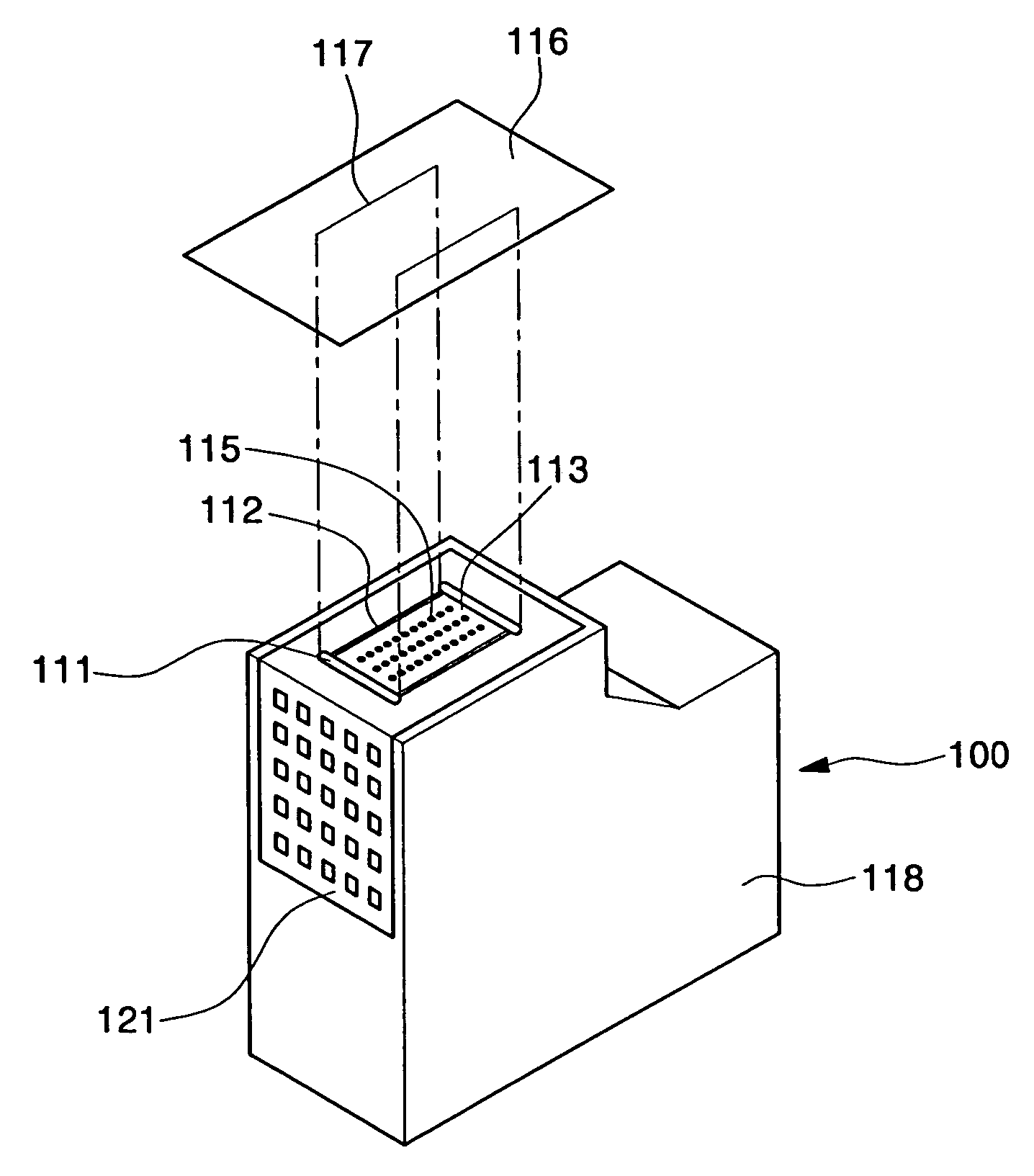
[0018] The nozzle tape may seal nozzles by forming the communication portion through which air may pass in the nozzle tape in order to prevent ink from leaking due to separation of the nozzle tape sealing the nozzles of the head chip as the air trapped in the spaced gap between the head chip and the head chip-mounting portion is expanded.
[0024] This has an effect capable of omitting a process of forming the communication portion by attaching the nozzle tape in a manner of exposing both ends of the spaced gap to the air, without directly forming the communication portion in the nozzle tape.

Problems solved by technology

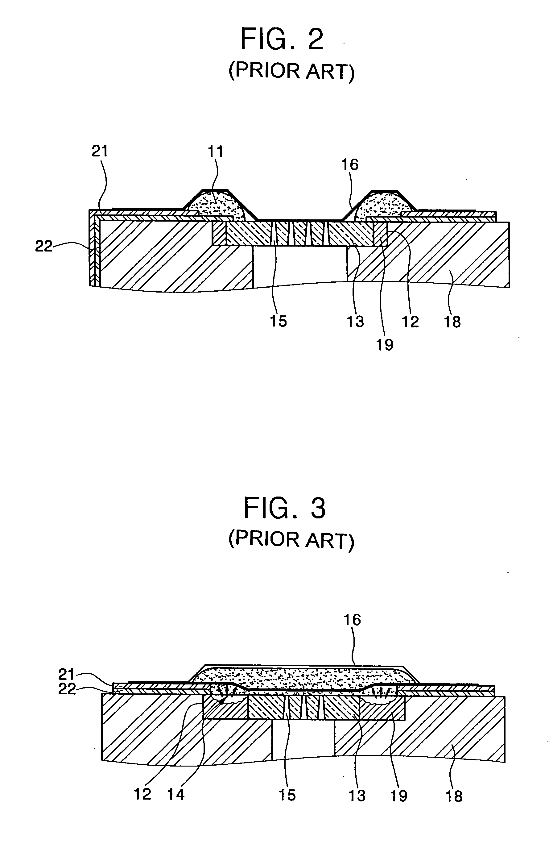
The leaked ink 30 not only causes various colors of the ink to be mixed but also breaks the meniscus of the ink due to a back flow through the nozzle 15, and the air is introduced into the head chip 13 through the nozzle 15, thereby causing a serious defect such as a loss of an ink supply function.
Although the slit in parallel with a bead member is formed in order to solve a separation problem of the polymer tape due to a gap between the polymer tape and the nozzle surface and an ink penetration through the gap, generated by the bead member protruding from the nozzle surface, a nozzle tape separation phenomenon generated by an air trap in two spaced gaps, at which the bead member is not formed, could not be solved.

Method used


Image

  • Nozzle tape used with inkjet cartridge
  • Nozzle tape used with inkjet cartridge
  • Nozzle tape used with inkjet cartridge

Examples


Embodiment Construction

[0037] Reference will now be made in detail to the embodiments of the present general inventive concept, examples of which are illustrated in the accompanying drawings, wherein like reference numerals refer to the like elements throughout. The embodiments are described below in order to explain the present general inventive concept by referring to the figures.

[0038]FIG. 5 is a perspective illustrating a state before a nozzle tape 116 is attached to an inkjet cartridge 100 in accordance with an embodiment of the present general inventive concept; and FIG. 6 is a plan view illustrating a state that the nozzle tape 110 is attached to the inkjet cartridge 100 of FIG. 3.

[0039] Referring to FIGS. 5 and 6, the inkjet cartridge 100 is provided with a head chip 113, having nozzles 115 for ejecting ink, mounted on a head chip-mounting portion 112 formed at one side of a cartridge body 118. Here, a spaced gap is formed between the head chip 113 and the head chip-mounting portion 112 due to t...


PUM


Abstract

A nozzle tape for an inkjet cartridge is attached to the inkjet cartridge including a head chip, a cartridge body provided with a head chip-mounting portion spaced apart from edges of the head chip by a predetermined extent, and at least one bead member protruded along the edges of the head chip, wherein the nozzle tape is provided with at least one communication portion in fluid communication with a spaced gap between the head chip and the head chip-mounting portion to make the air trapped under the nozzle tape communicate with external air through the communication portion, thereby tightly attaching the nozzle tape to the nozzles, regardless of changes of an external environment.

Description

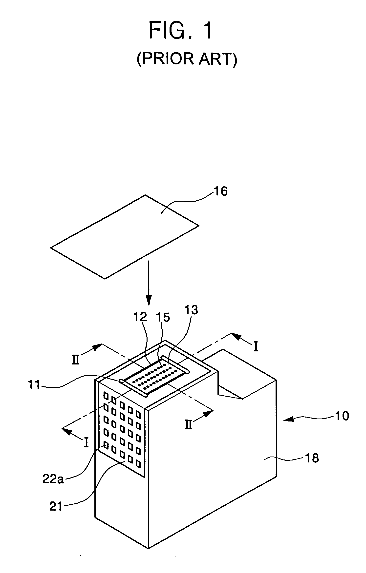
CROSS-REFERENCE TO RELATED APPLICATIONS [0001] This application claims the benefit of Korean Patent Application No. 2004-51456 filed on Jul. 12, 2004, the disclosure of which is hereby incorporated herein by reference in its entirety. BACKGROUND OF THE INVENTION [0002] 1. Field of the Invention [0003] The present general inventive concept relates to an apparatus to seal a head chip nozzle of an inkjet cartridge in an image forming, and more particularly, to a nozzle tape to seal a nozzle surface of a head chip in order to prevent ink from leaking out of an inkjet cartridge during transportation and storage of the inkjet cartridge after the inkjet cartridge is assembled. [0004] 2. Description of the Related Art [0005]FIG. 1 is a perspective view illustrating a state before a nozzle tape 16 is attached to a conventional inkjet cartridge 10, FIG. 2 is a cross-sectional view taken along a line I-I of FIG. 1, and FIG. 3 is a cross-sectional view taken along a line II-II of FIG. 1. [0006]...

Claims


Application Information

Patent Timeline
Patent Type & Authority Applications(United States)
IPC IPC(8): B41J2/175
CPCB41J2/17536B41J2/1753B41J2/16505
Inventor LEE, JAE-CHEOL
Owner S PRINTING SOLUTION CO LTD
Learn More