
Heat exchanger for air conditioner

a technology of heat exchanger and air conditioner, which is applied in the direction of indirect heat exchanger, light and heating apparatus, transportation and packaging, etc., can solve the problems of difficult to secure a uniform surface pressure throughout the entire length of seal material, high cost, and high cost, and achieve excellent wiring performance of the outer fluid pipe and excellent working factor of the piping connection.

Inactive Publication Date: 2006-01-12
DENSO CORP
View PDF2 Cites 19 Cited by
  • Summary
  • Abstract
  • Description
  • Claims
  • Application Information

AI Technical Summary

Benefits of technology

[0015] It is another object of the invention to provide a piping connection structure for charging and discharging a heat source fluid having high seal performance in the rotary air conditioning heat exchanger.
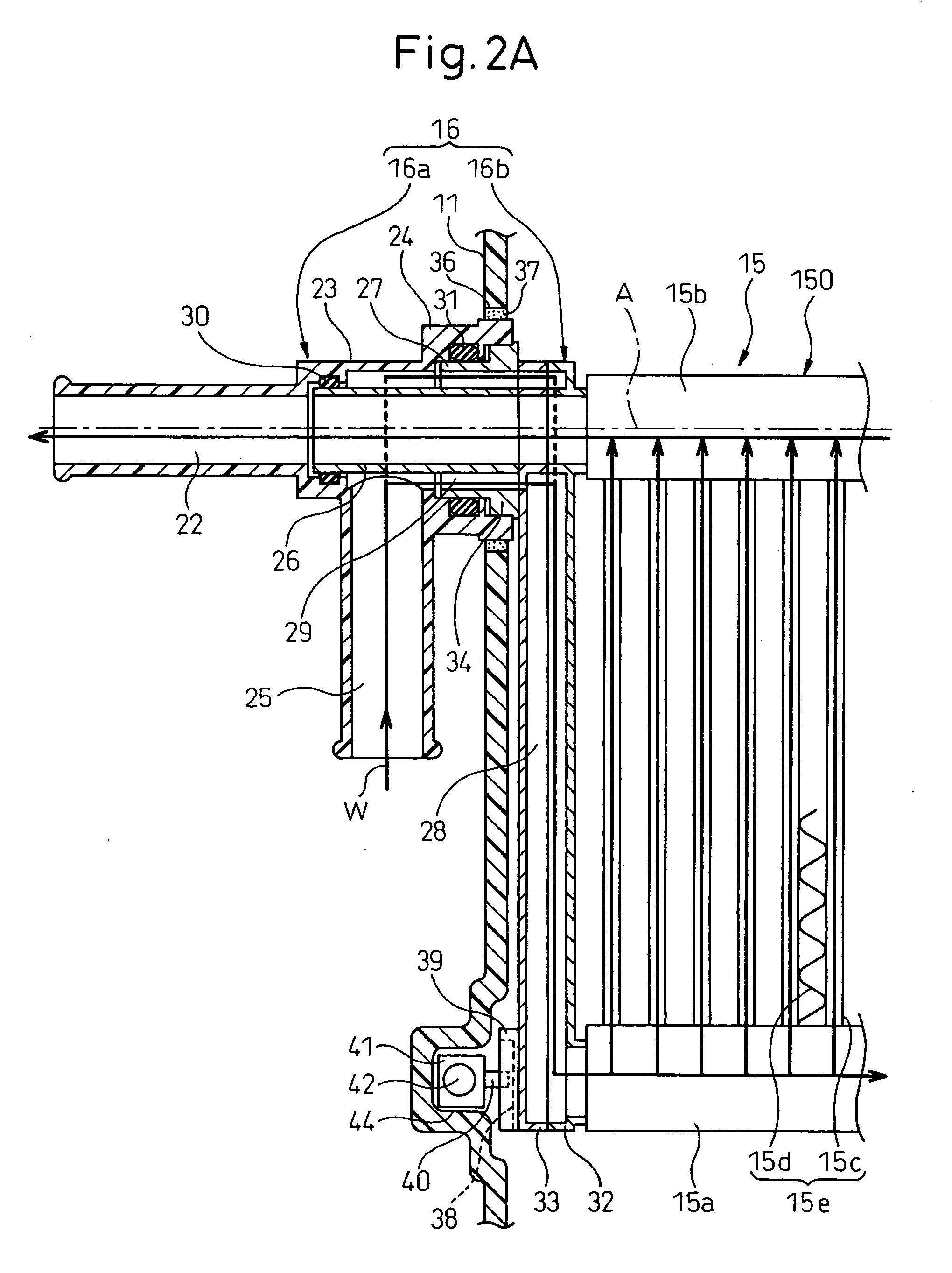
[0057] One fixed side inlet pipe (23) distributes the heat source fluid to the two air conditioning heat exchangers (15) and the fixed side outlet pipe (22) gathers the heat source fluids from the two air conditioning heat exchangers (15). Therefore, the connection portion of the outer fluid pipe connected to the outlet / input pipe on the side of the heat exchangers can be gathered to one position. Accordingly, in the independent control system car air conditioner, the trouble of connecting the outer fluid pipe to the two air conditioning heater exchangers (15) can be eliminated and the working factor of piping connection is high.

Problems solved by technology

Therefore, the diameters of both disc-like members become unavoidably large.
Because the surface seal structure in which the seal member is clamped between disc-like members is employed, it is difficult to secure a uniform surface pressure throughout the entire length of the seal material and seal defect is likely to occur.
Therefore, a connection work of the fixed side pipe and the rotation side pipe must be carried out on both sides of the heat exchanger for heating and the assembly work factor is deteriorated.
Because the hot water inlet pipe and the hot water outlet pipe protrude in mutually opposite directions, the arrangement performance of these hot water pipe is deteriorated, too.
The same problem occurs also when the cooling heat exchanger itself is allowed to rotate and to play the role of the air-mix door.

Method used


Image

  • Heat exchanger for air conditioner
  • Heat exchanger for air conditioner
  • Heat exchanger for air conditioner

Examples


first embodiment

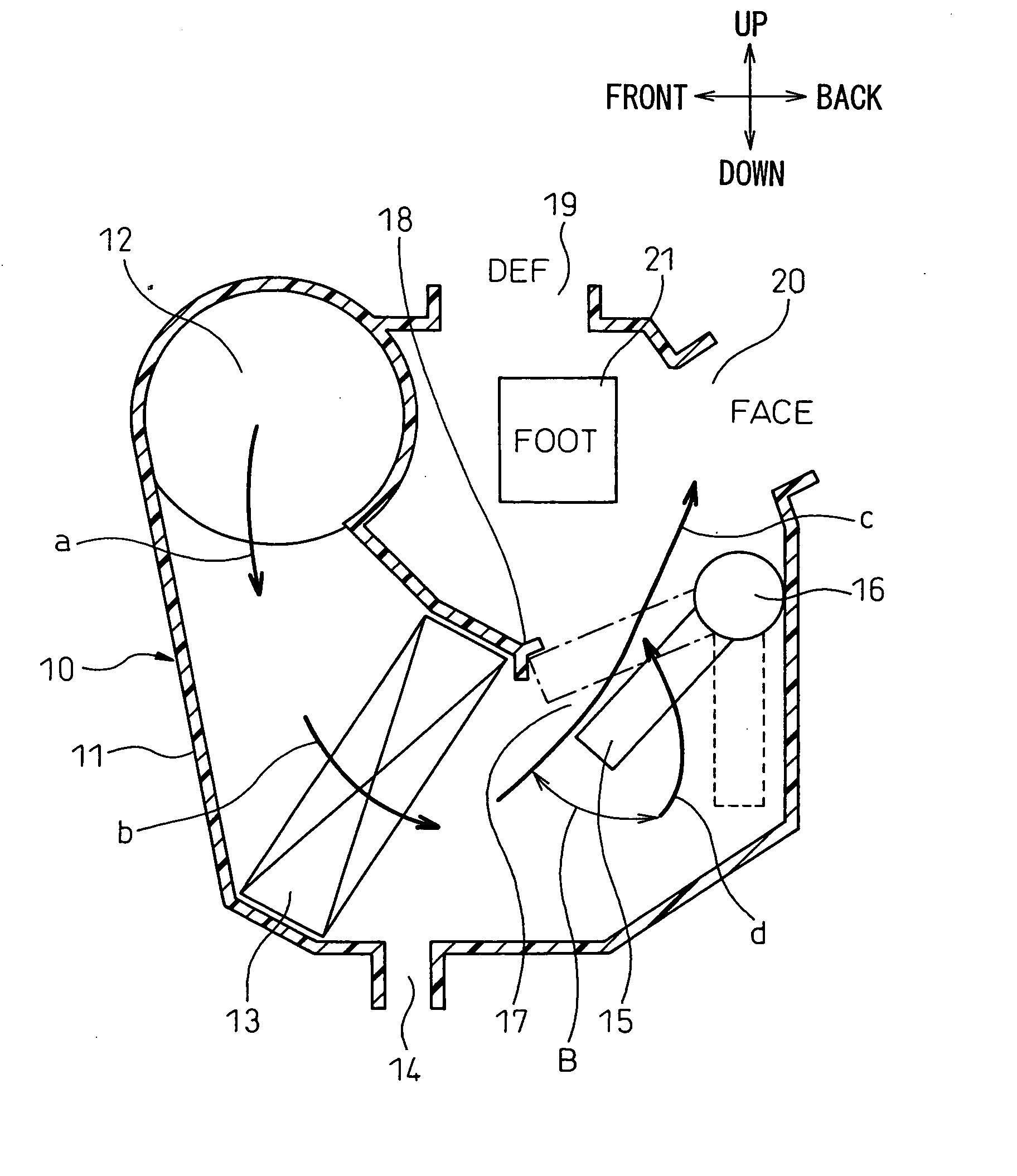
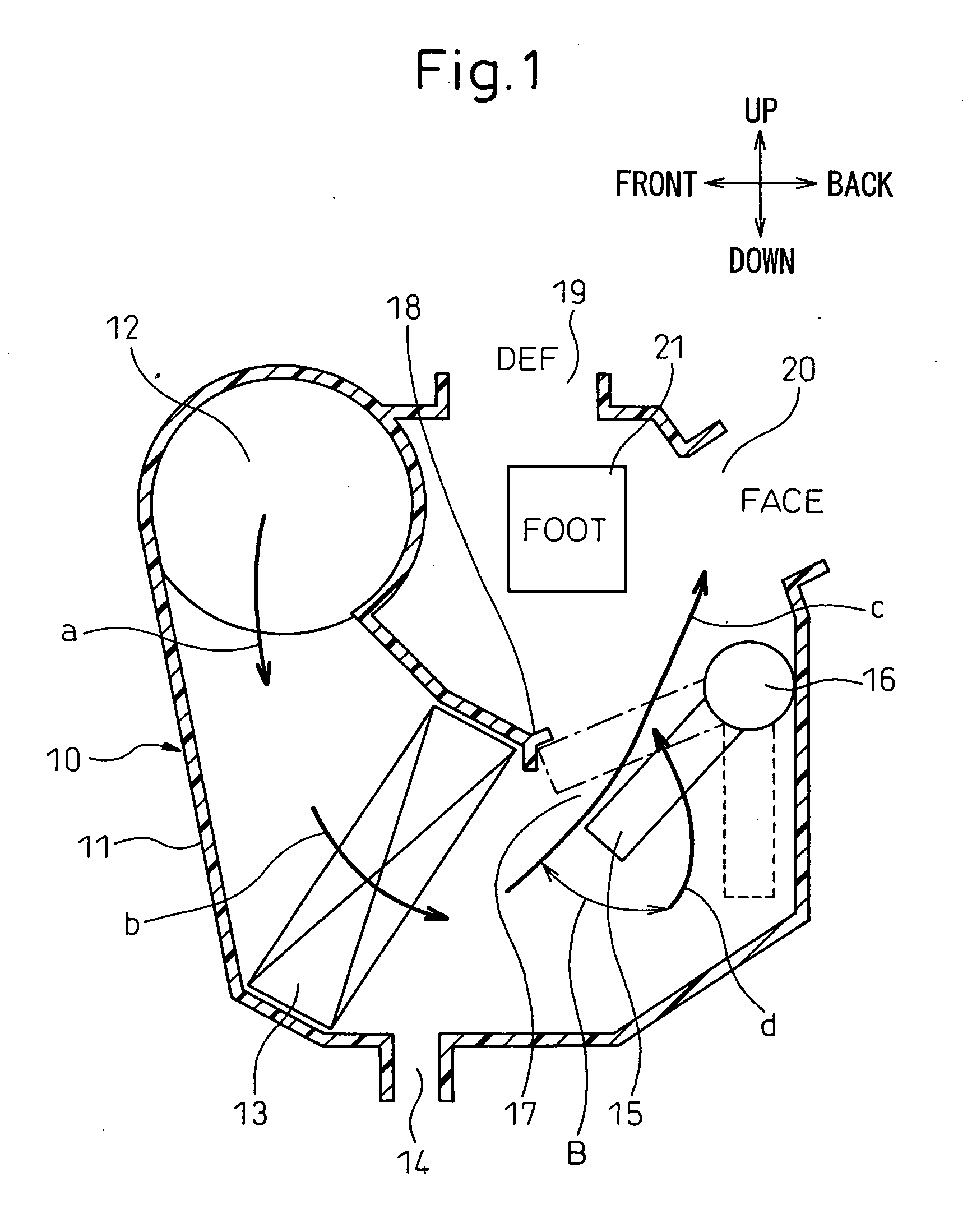
[0076] FIGS. 1 to 4 show the first embodiment of the invention. FIG. 1 is a schematic sectional view of a air conditioning unit in a passenger compartment for a car air conditioner having a rotary-type heat exchanger for heating according to the first embodiment of the invention. FIG. 2A is a sectional view of principal portions of the rotary-type heat exchanger for heating in the first embodiment. FIG. 2B is an enlarged view of an outer leak seal mechanism portion in the rotary heat exchanger for heating. FIG. 3 is a schematic arrangement view of a rotation driving mechanism of the rotary heat exchanger for heating. FIG. 4A is a perspective view of a fixed side of a coaxial double-piping portion for charging and discharging hot water of the rotary heat exchanger for heating in the first embodiment and FIG. 4B is a perspective view of a rotary side portion.

[0077] First, an outline of the air conditioning unit 10 for the passenger compartment in the car air conditioner will be expla...

second embodiment

[0144] In the foregoing first embodiment, the rotary portion 16b shown in FIG. 4B is integrated with the heat exchanger main body 150 of the heater core 15 by brazing. In the second embodiment, the rotary portion 16b is in advance assembled into a unitary component by brazing, bonding, etc, while substantially cylindrical connection members 45 and 46 are integrally brazed with the end portions of both tanks 15a and 15b of the heat exchanger main body 150 of the heater core 15 in the longitudinal direction.

[0145] The end portion of the inner pipe 26 of the rotary portion 16b is fitted to the inner peripheral side of the connection member 45 through a sealant, not shown, and the connection member 45 is then caulked to seal and fix the end portion of the inner pipe 26 to the connection member 45. In consequence, the inner pipe 26 can be communicated with the inside of the hot water outlet tank 15b through the substantially cylindrical connection member 45.

[0146] Similarly, the cylind...

third embodiment

[0149] In the foregoing first embodiment, the coaxial double-piping portion 16 for charging and discharging hot water is arranged on one of the end sides of the heater core 15 (on the side of the hot water outlet tank 15b) and the rotation center axis A of the heater core 15 is set on one of the end sides of the heater core 15 (on the side of the hot water outlet tank 15b). In the third embodiment, however, the coaxial double-piping portion 16 for charging and discharging hot water is set to an intermediate position of the communication pipe 28 in the longitudinal direction and the rotation center axis A of the heater core 15 is set to an intermediate position between the hot water inlet tank 15a and hot water outlet tank 15b of the heater core 15 as shown in FIG. 6.

[0150]FIG. 7 shows a concrete example of the air conditioner unit 10 when the rotation center axis A of the heater core 15 is set to the intermediate position between the hot water inlet tank 15a of the heater core 15 a...


PUM


Abstract

A heat source fluid inlet pipe of a heat exchanger main body 150 comprises a rotation side inlet pipe 27 and a fixed side inlet pipe 23 that are integrated with the heat exchanger main body 150. A heat source fluid outlet pipe comprises a rotation side outlet pipe 26 and a fixed side outlet pipe 22 that are integrated with the heat exchanger main body 150. These pipes 22, 23, 26 and 27 are constituted into a coaxial double-piping structure 16 and the heat exchanger main body 150 is allowed to rotate with a center axis A of this coaxial double-piping structure 16 as the center.

Description

BCKGROUND OF THE INVENTION [0001] 1. Field of the Invention [0002] This invention relates to a coaxial double piping structure for charging and discharging a heat source fluid in an air conditioning heat exchanger used as means for heat-exchanging air in a car. More particularly, the invention is effective when it is applied to an air conditioning heat exchanger of the type in which the air conditioning heat exchanger itself is so constituted as to be capable of rotating. [0003] 2. Description of the Related Art [0004] An air-mix-type, that regulates the ratio of cold air and warm air by using an air-mix door and adjusts a temperature of air blowing to a passenger compartment, is a typical example of a temperature regulation system of an air conditioner for a car. [0005] In this air-mix-type air condition for a car, Japanese Unexamined Patent Publications No. 2001-47845 and No. 2001-246921 disclose an air conditioner in which a hot-water-type heat exchanger for heating is so constit...

Claims


Application Information

Patent Timeline
IPC IPC(8): F28F27/02B60H3/00B61D27/00B60H1/00F28F5/00
CPCB60H1/00328B60H2001/0035F28D1/05366F28D1/05375F28F2280/10F28F9/0246F28F9/0248F28F9/0253F28D2021/0096
Inventor MAEDA, KENICHIROUEMURA, YUKIOKAJIYA, KEI
Owner DENSO CORP
Learn More