Facet joint fusion devices and methods
- Summary
- Abstract
- Description
- Claims
- Application Information
AI Technical Summary
Benefits of technology
Problems solved by technology
Method used
Image
Examples
Embodiment Construction
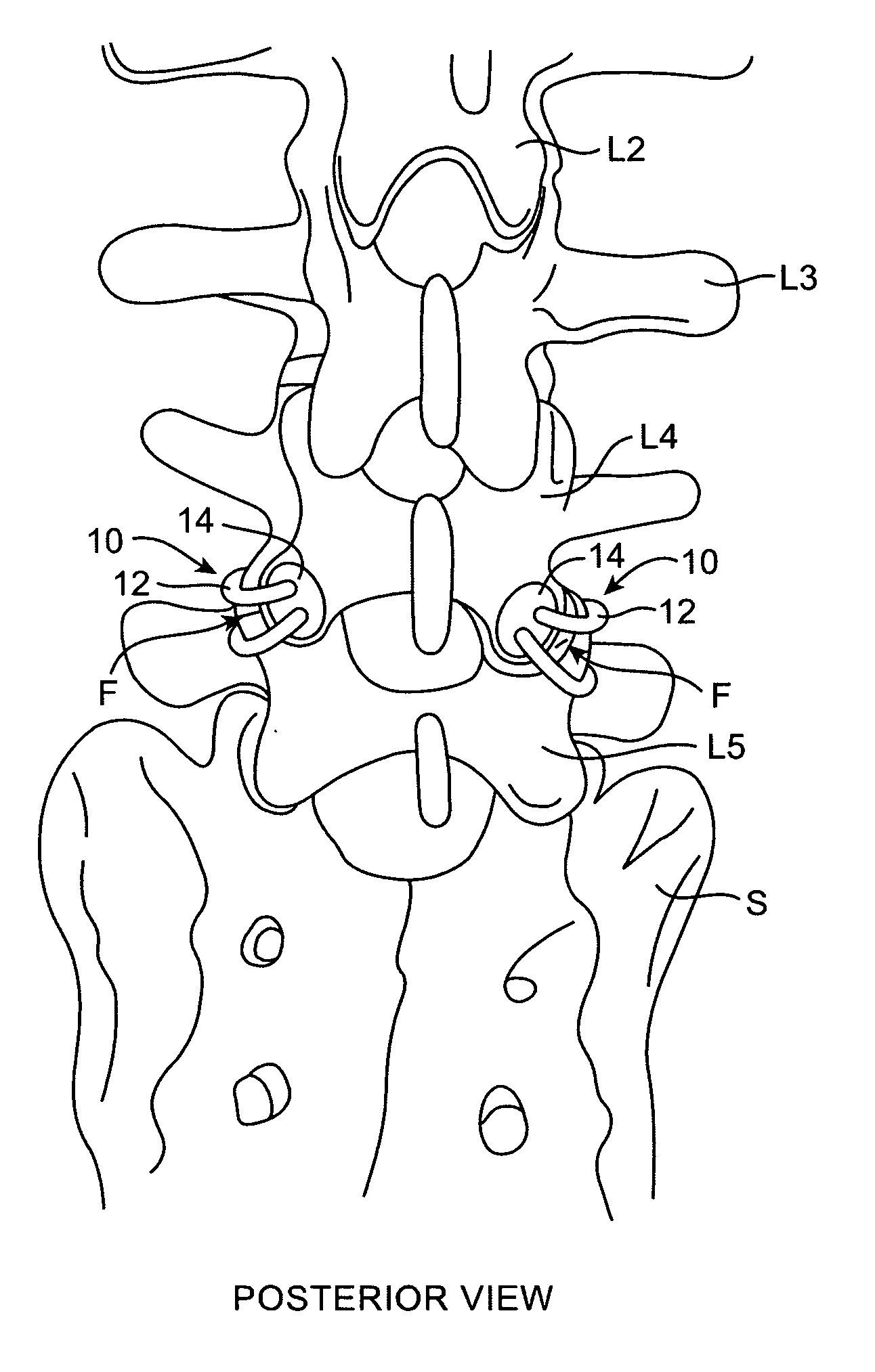
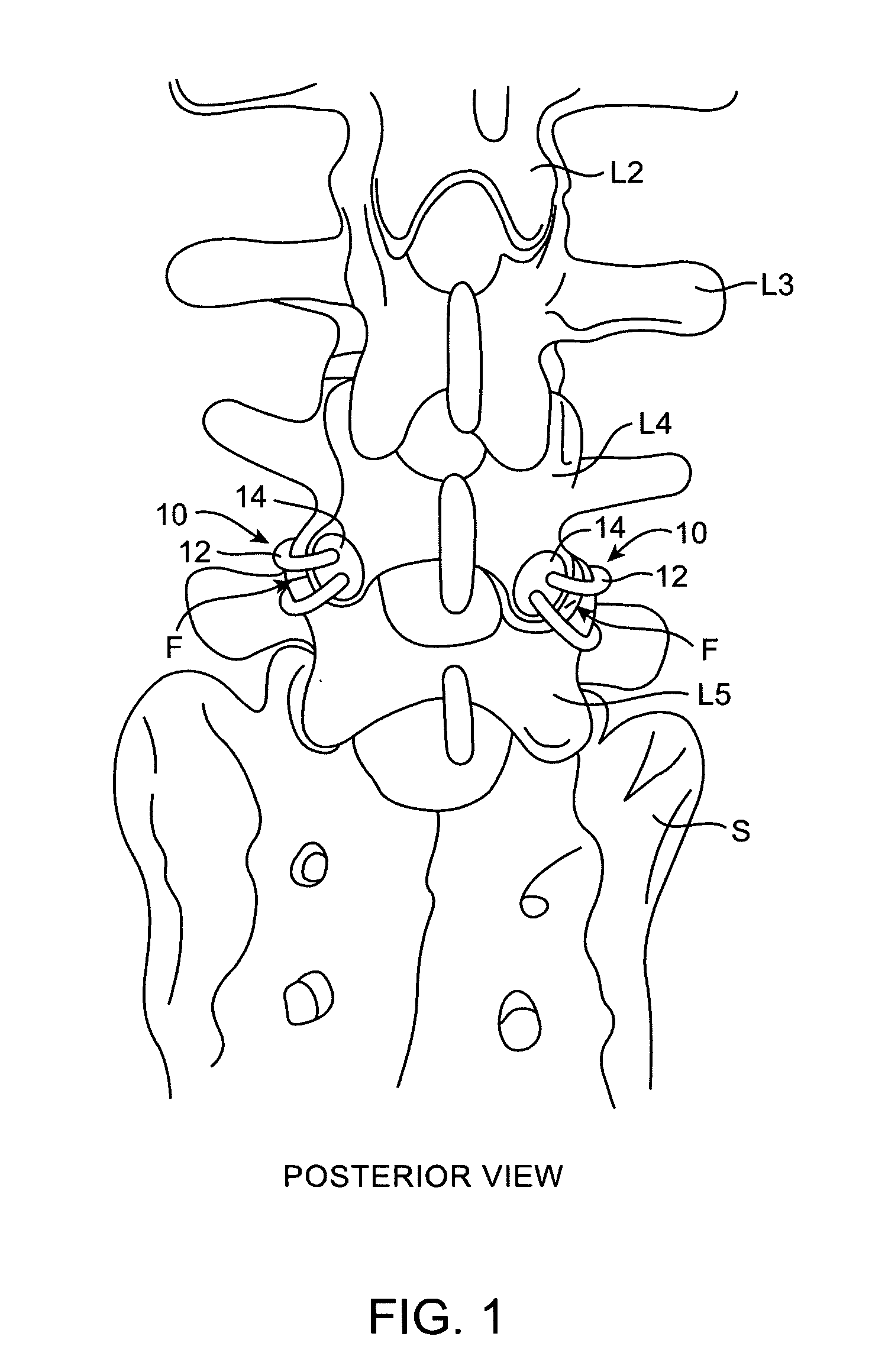
[0045]FIG. 1 is a posterior perspective view of the most inferior four lumbar vertebrae (L2-L5) and a portion of the sacrum S. Attached across the two facet joints F between the L4 and L5 vertebrae is a clamping device 10 according to one embodiment of the present invention. Each clamping device 10 includes a tether 12 and two bone surface contacting members 14 (only one contacting member 14 is visible for each device 10 in FIG. 1.) As is described in further detail below, two holes are drilled through each of the facet joints F of L4 and L5, tethers 12, coupled with bone contacting members 14, are passed through the holes, and tethers 12 are cinched to apply compressive force across the facet joints F, thus promoting fusion of and / or stabilizing the joints F.
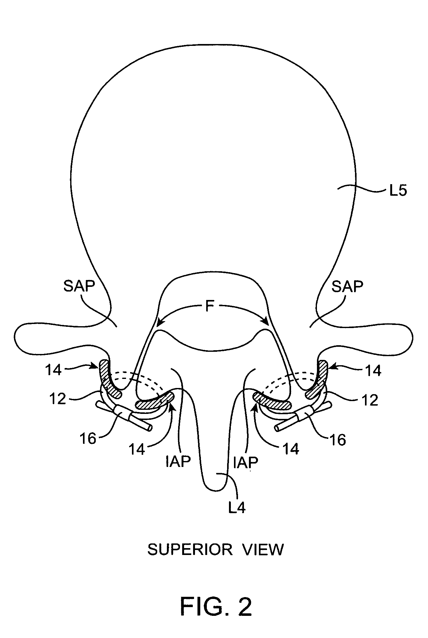
[0046]FIGS. 2 and 3 provide superior and lateral views, respectively, of clamping device 10 from FIG. 1. In FIG. 2, it can be seen that tethers 12 extend through holes (dotted lines) in the vertebrae L4, L5 and across the face...
PUM
 Abstract
Description
Claims
Application Information
 - R&D
- Intellectual Property
- Life Sciences
- Materials
- Tech Scout
- Unparalleled Data Quality
- Higher Quality Content
- 60% Fewer Hallucinations
Browse by: Latest US Patents, China's latest patents, Technical Efficacy Thesaurus, Application Domain, Technology Topic, Popular Technical Reports.
© 2025 PatSnap. All rights reserved.Legal|Privacy policy|Modern Slavery Act Transparency Statement|Sitemap|About US| Contact US: help@patsnap.com


