
Shift control apparatus for automatic transmission

a technology of automatic transmission and control apparatus, which is applied in the direction of electric control, machines/engines, transportation and packaging, etc., can solve the problems of generating shift shock, conveying an uncomfortable sensation to the driver, and it is difficult to optimally adapt such control to all downshifts, etc., and achieves the effect of reducing the amount of engine outpu

Inactive Publication Date: 2006-01-05
AISIN AW CO LTD
View PDF4 Cites 11 Cited by
  • Summary
  • Abstract
  • Description
  • Claims
  • Application Information

AI Technical Summary

Benefits of technology

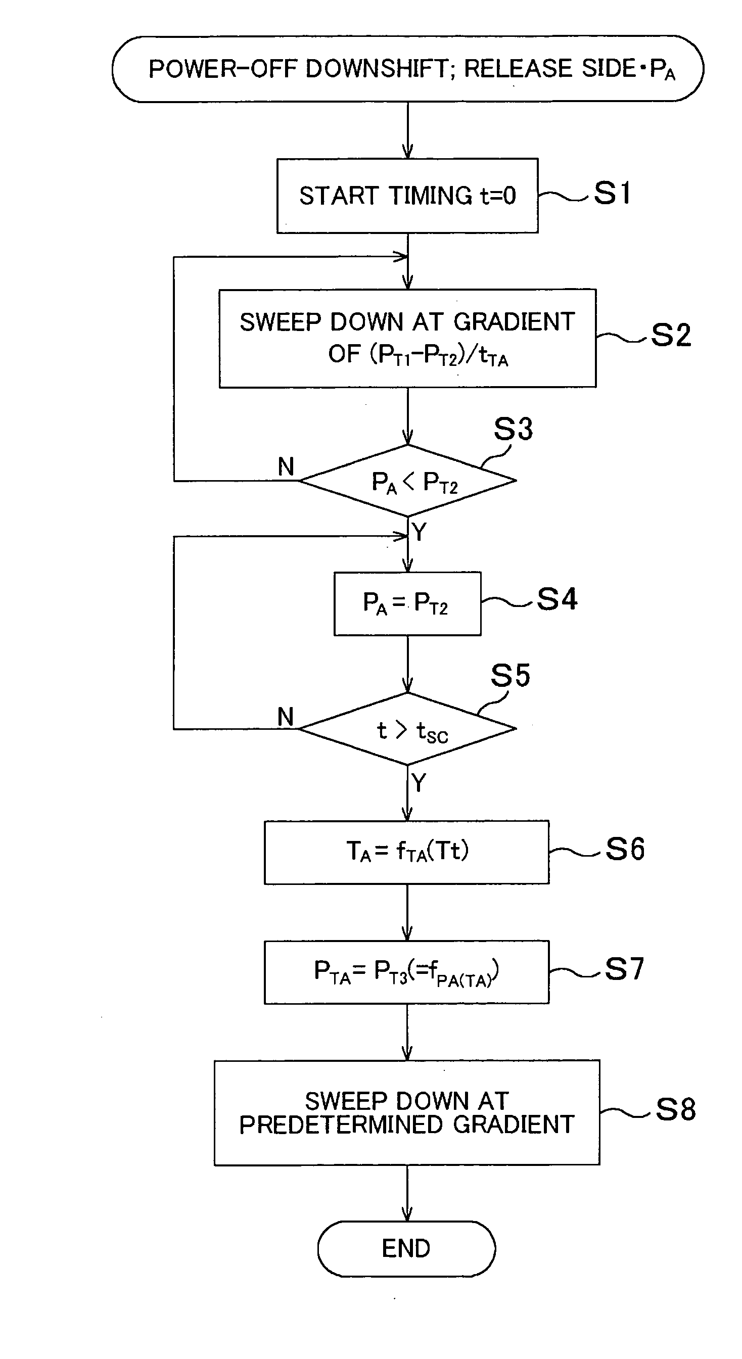
[0009] According to a first aspect, the present invention provides control of the increase in engine output, which is always appropriate for the particular downshift by selecting and executing an engine output increase control scheme which is stored in memory in correlation with the type of downshift. Furthermore, duration of a power-off downshift is reduced without any adverse sensation caused by an excessive increase in engine torque.
[0011] According to a third aspect, the present invention provides engine output control which increases the engine output by an amount that is always appropriate for the type of downshift.
[0012] According to a fourth aspect, the present invention changes both the start of timing of the engine output control and the amount of increase of the engine output. As a result, engine output control which is appropriate overall can be selected according to the type of downshift. For example, in the case of a skip downshift, as compared with a normal downshift, the start of timing is advanced and the increase in the amount of engine output is reduced.

Problems solved by technology

Thus, as the shift duration increases so does the friction energy expended by the frictional engagement device, causing its friction elements to wear faster.
However, even if engine output is appropriately increased with accurate timing in a predetermined downshift of, for example, 3rd speed to 2nd speed, by changing the duration of the timed predetermined period, it is still difficult to optimally adapt such control to all downshifts.
Therefore, engine control with inappropriate timing and with an inappropriate amount of torque increase may place the engine in a driving (i.e., power-on) state, which may convey an uncomfortable sensation to the driver or generate shift shock.

Method used


Image

  • Shift control apparatus for automatic transmission
  • Shift control apparatus for automatic transmission
  • Shift control apparatus for automatic transmission

Examples


Embodiment Construction

[0027] Preferred embodiments of the present invention will hereinafter be described with reference to the appended drawings.

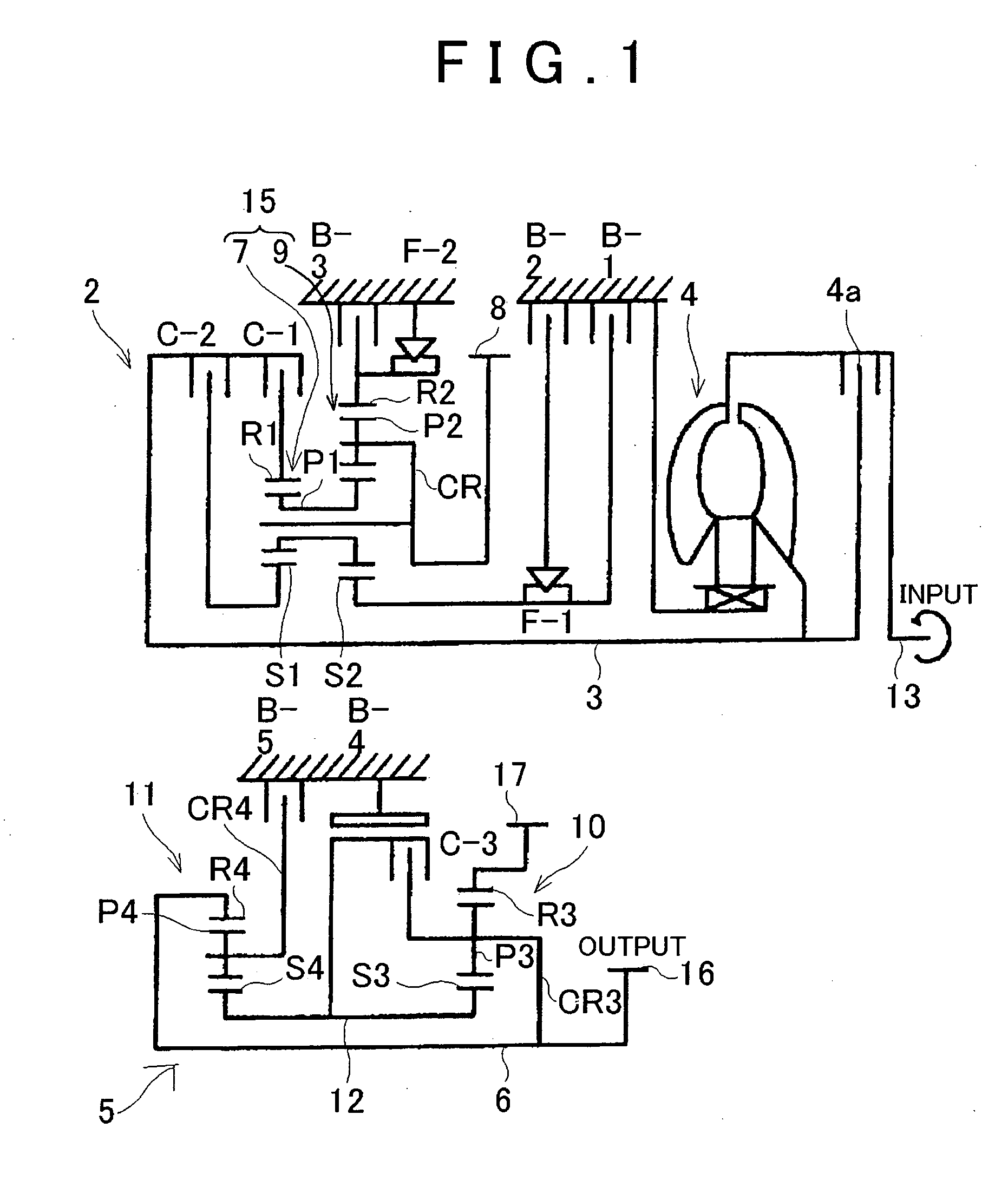
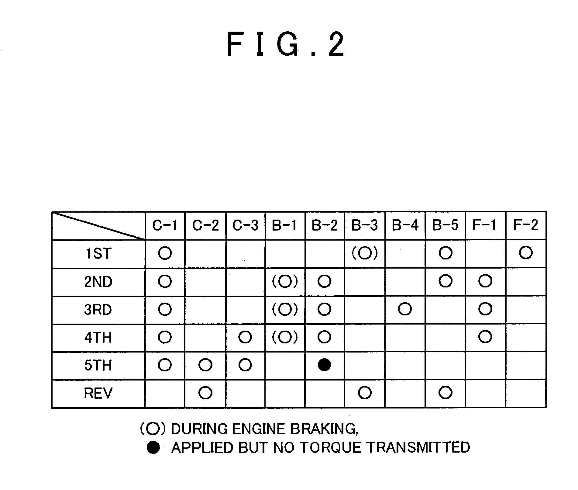
[0028]FIG. 1 shows a five-speed automatic transmission 1 as including a torque converter 4, a three-speed main speed change mechanism 2, a three-speed auxiliary speed change mechanism 5, and a differential (not shown), all of which are joined together and housed in an integrated (“integral”) case. The torque converter 4 is provided with a lock-up clutch 4a and transmits rotational force from an engine crankshaft 13 to an input shaft 3 of the main speed change mechanism 2, either via hydraulic fluid within the torque converter 4 or via a mechanical connection established by engagement of the lock-up clutch. The first shaft 3 (more specifically, the input shaft) which is aligned with the crankshaft 13, a second shaft 6 (a counter shaft) which is parallel to the first shaft 3, and a third shaft (a differential left / right output shaft) are all rotatably supported ...


PUM


Abstract

An engine output controller includes a delay timer which measures the period of time elapsed from a timing of a target hydraulic pressure of a release side hydraulic pressure, and control starts a predetermined period of time after a predetermined amount of torque increase is achieved. The engine output control stores maps of the predetermined periods of time and the amounts of torque increase corresponding to normal shifts, such as 3rd to 2nd and 4th to 3rd, and skip-shifts, such as 4th to 2nd, and selects the map corresponding to the type of downshift.

Description

CROSS-REFERENCE TO RELATED APPLICATION [0001] This application claims, under 35 USC 119, priority of Japanese Application No. 2004-195842 filed Jul. 1, 2004, the teachings of which are incorporated by reference herein in their entirety, inclusive of the specification, claims and drawings. BACKGROUND OF THE INVENTION [0002] 1. Field of the Invention [0003] The present invention relates to a shift control apparatus for an automatic transmission. More particularly, the present invention relates to a shift control apparatus which performs a downshift when an accelerator is off (i.e., during power-off), more specifically, which controls engine output during a downshift. [0004] 2. Description of the Related Art [0005] Typically in a vehicle having an automatic transmission, when sufficient engine braking force is unable to be obtained when the accelerator is off (i.e., power-off), when traveling down a slope or the like, a driver routinely downshifts by either shifting a shift lever from ...

Claims


Application Information

Patent Timeline
Patent Type & Authority Applications(United States)
IPC IPC(8): B60K41/04B60W10/00B60W10/04B60W10/06B60W10/10B60W10/11B60W10/115F02D29/00F02D41/04F16H59/18F16H59/70F16H61/04F16H61/68F16H61/684F16H61/686F16H63/50
CPCF16H61/061F16H61/686F16H63/502F16H2061/0444Y10T477/675Y10T477/68Y10T477/6808Y10T477/6937F16H2061/0496
Inventor INAGAKI, NOBUAKIITO, EIJI
Owner AISIN AW CO LTD
Learn More