Eureka AIR delivers breakthrough ideas for toughest innovation challenges, trusted by R&D personnel around the world.

Gas heat-pump system

a heat pump and gas technology, applied in heat pumps, lighting and heating apparatus, electric control, etc., can solve the problem that the operation cannot be actively performed according to a load change on an air conditioning module, and achieve the effect of improving the efficiency of the gas heat pump system, reducing the amount of discharged exhaust gas, and increasing the output of the engin

Active Publication Date: 2021-06-10
LG ELECTRONICS INC
View PDF2 Cites 0 Cited by
  • Summary
  • Abstract
  • Description
  • Claims
  • Application Information

AI Technical Summary

Benefits of technology

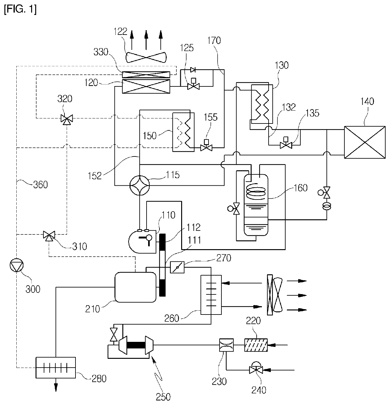
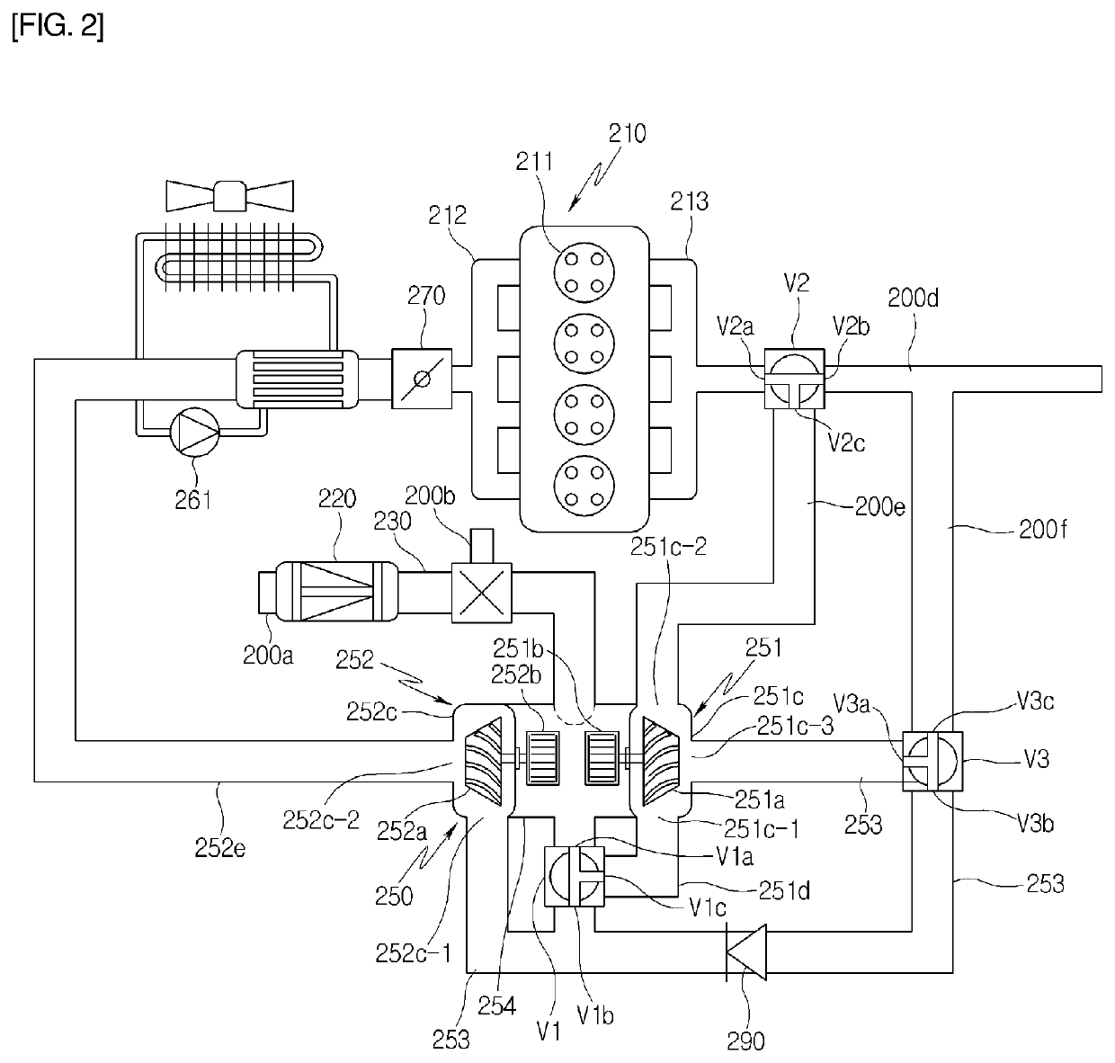
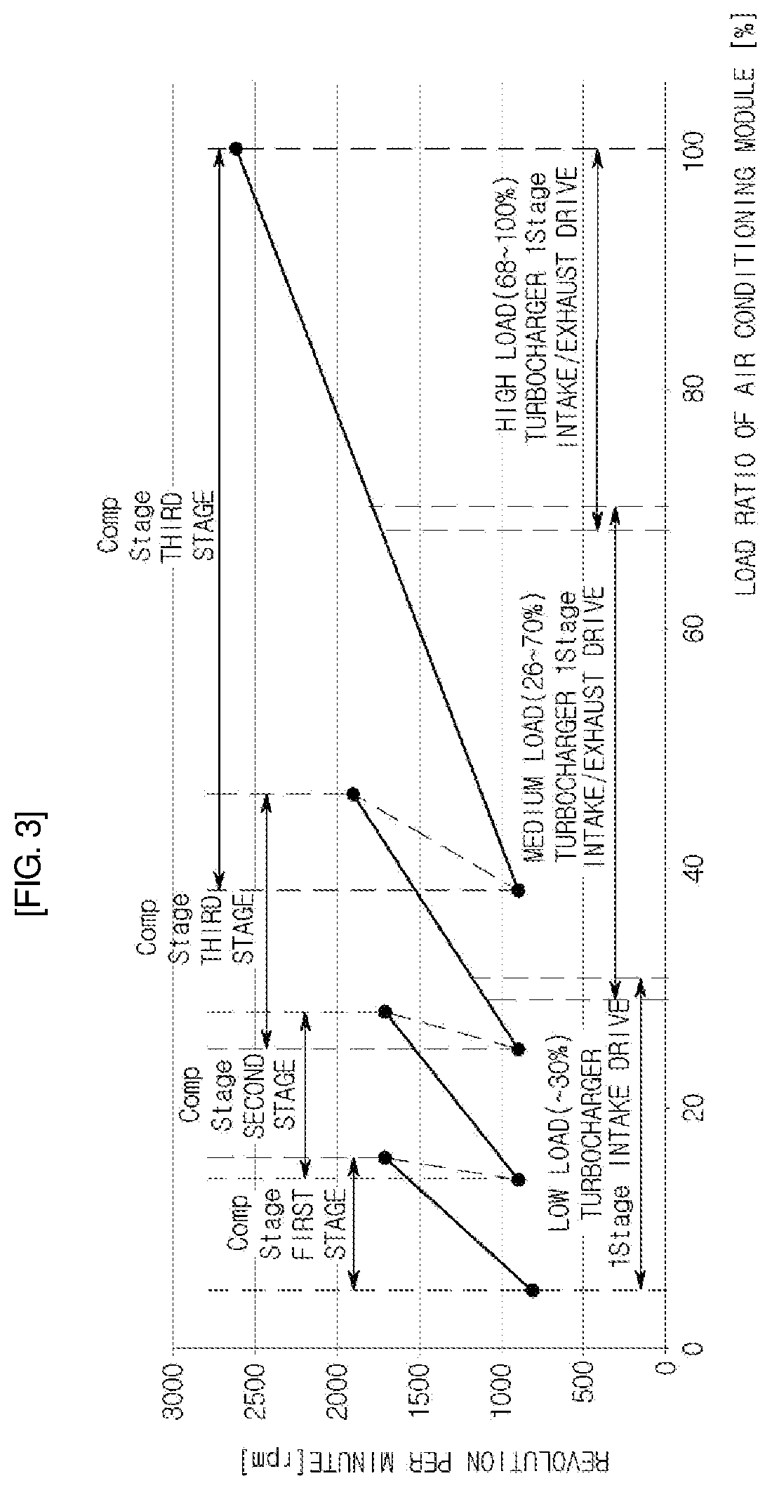
The present patent aims to provide a gas heat-pump system that can switch between a first-stage turbocharging mode and a second-stage turbocharging mode based on the load ratio of the air conditioning module. The system includes first and second turbochargers that can operate independently, resulting in more efficient operation in response to changes in load. Additionally, the system guides exhaust gas towards a fuel-to-air mixture using the turbocharger, reducing the amount of exhaust gas and increasing engine output. These technical effects improve the performance and efficiency of the gas heat-pump system.

Problems solved by technology

However, in the configuration disclosed in Patent Document 1, because the driving of the turbocharger depends only on the exhaust gas from the engine, operation cannot be actively performed according to a change in load on an air conditioning module.

Method used


Image

  • Gas heat-pump system
  • Gas heat-pump system
  • Gas heat-pump system

Examples


Embodiment Construction

[0052]Exemplary embodiments of the present disclosure will be described in detail below with reference to the accompanying drawings.

[0053]Various modifications can be made to the present disclosure, and thus various embodiments can be implemented. The resulting specific embodiments will also be described in detail below with reference to the drawings. This description is not intended to limit the present disclosure to the specific embodiments. All alterations, equivalents, and substitutes that are included within the technical idea of the present disclosure should be construed as falling within the scope of the present disclosure.

[0054]The terms first and second, and so on are used to describe various constituent elements, but should not be construed as imposing any limitation on the various constituent elements. These terms are used only to distinguish one element from another. For example, a first constituent element may be expressed as a second constituent element without departi...


PUM


Abstract

Proposed is a gas heat-pump system including: a compressor of an air conditioning module; a gas engine generating a drive force of the compressor; and a turbocharger primarily first-level pressure to a fuel-to-air mixture and supplying the fuel-to-air mixture to the gas engine or applying second-level pressure to the fuel-to-air mixture to which the first-level pressure is applied and supplying the fuel-to-air mixture to the gas engine.

Description

CROSS REFERENCE TO RELATED APPLICATION[0001]The present application claims priority to Korean Patent Application No. 10-2019-0161649, filed Dec. 6, 2019, the entire contents of which is incorporated herein for all purposes by this reference.BACKGROUND OF THE INVENTIONField of the Invention[0002]The present disclosure relates to a gas heat-pump system and, more particularly, to a gas heat-pump system in which switching to a first-stage turbocharge mode or a second-stage turbocharge mode takes place according to a required load ratio of an air conditioning module, and in which a first turbocharger and a second turbocharger, which are drivable independently of each other, operate in the first-stage turbocharge mode or the second-stage turbocharge mode. Thus, the first and second turbochargers can actively operate in a manner that corresponds to a change in load, and the efficiency of the gas heat-pump system can be improved.Description of the Related Art[0003]A heat-pump system is a sy...

Claims


Application Information

Patent Timeline
Patent Type & Authority Applications(United States)
IPC IPC(8): F25B27/00F02B33/40F02B39/10F02B47/08F02M26/08F02D23/00F02D29/04
CPCF25B27/00F02B33/40F02B39/10F02D29/04F02M26/08F02D23/00F02B47/08F02D41/0007F02D41/021F02B41/10Y02T10/12F02B37/12F02M26/52F25B30/02F25B2327/001F02D2200/101
Inventor JANG, HEEJOONGJEONG, HOJONG
Owner LG ELECTRONICS INC
Why Eureka
Eureka Blog
Learn More