Ferrite core, and flexible assembly of ferrite cores for suppressing electromagnetic interference
a technology of ferrite core and ferrite core, which is applied in the direction of inductance, inductance with magnetic core, transformer/inductance details, etc., can solve the problems of increasing the noise level of electromagnetic environment, creating electromagnetic interference (emi), and brittleness of sintered ferrite material,
- Summary
- Abstract
- Description
- Claims
- Application Information
AI Technical Summary
Benefits of technology
Problems solved by technology
Method used
Image

Examples
first embodiment
The First Embodiment
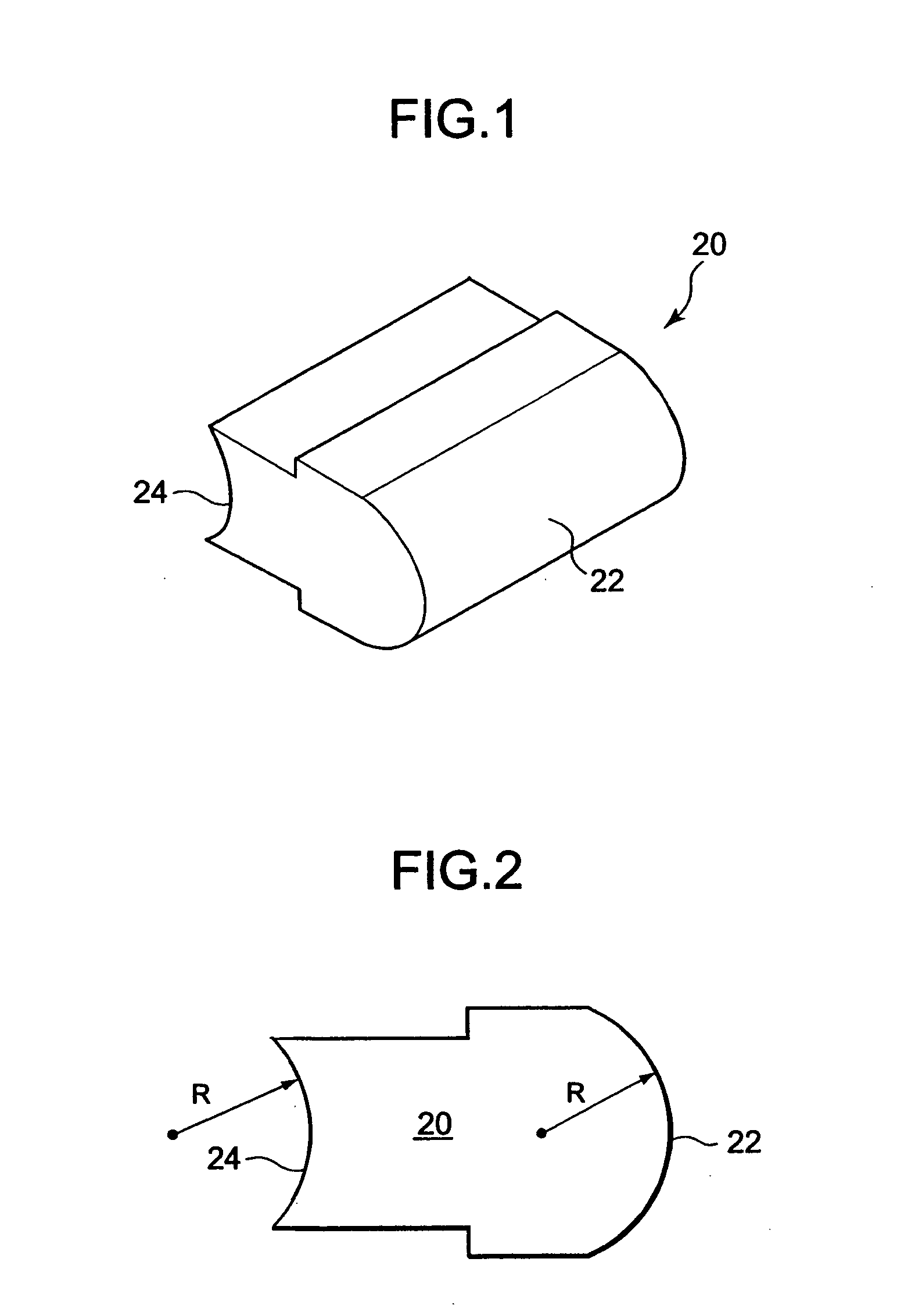
[0032] With initial reference to FIGS. 1 and 2, a ferrite core 20 has a front or head end 22 and a back or tail end 24. The head end 22 has a curved, convex shape and the tail end 24 has a curved, concave shape. Specifically, the head end 22 is shaped as a segment of the cylinder having a radius R and, similarly, the tail end 24 is shaped as a segment of the cylinder having the radius R or a radius slightly greater than R. It will be apparent, then, that the head end 22 of one ferrite core 20 can be accommodated in a recess provided at the tail end 24 of an adjacent ferrite core in a manner of a cylinder-and-socket joint.
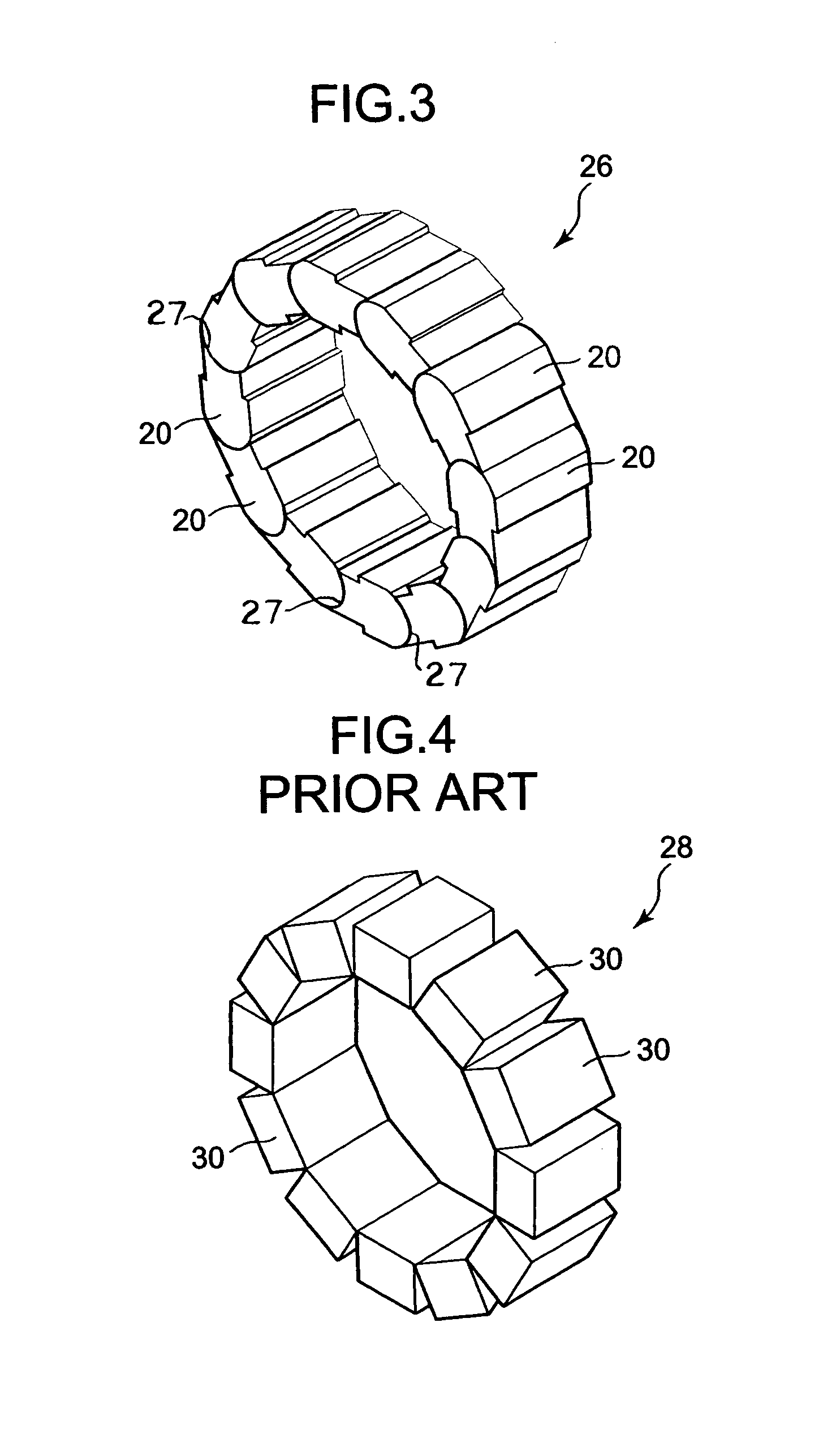
[0033]FIG. 3 illustrates an example of a ferrite core assembly 26 formed by a number of ferrite cores 20 that had been arranged, head-end to tail-end, in a toroidal configuration. Since the head ends fit snuggly against the tail ends of the ferrite cores 20, the gaps 27 between the ferrite cores have minimal gap widths. The core assemblies 26 co...
second embodiment
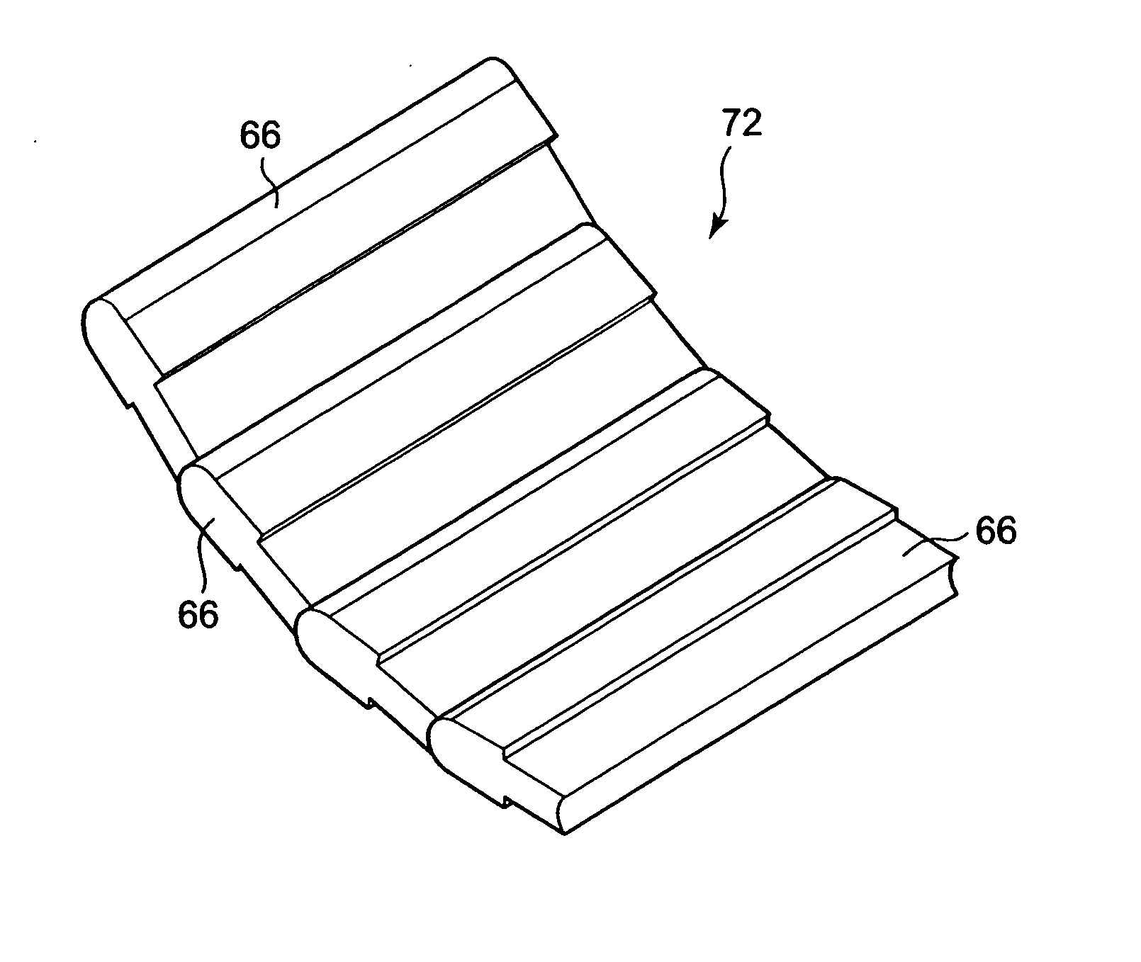
[0041]FIG. 10 illustrates a second embodiment of a ferrite core in accordance with the present invention. The core 66 is similar to the core 20 shown in FIG. 1, but it has a width that is substantially greater.
[0042] The ferrite core 66 has a front or head end 68 with a curved, convex shape and a back or tail end 70 with a curved, concave shape. The head and tail end 70 are each configured as segments of a cylinder having approximately the same radius.
[0043]FIG. 11 illustrates several of the ferrite cores 66 arranged, head-end to tail-end, to provide a ferrite core assembly 72. The core assembly 72 may be packaged using a variety of techniques, including those shown in FIGS. 6-9.
[0044] In use, the core assembly 72 can be attached to the face of a flat cable 74 (such as a ribbon cable or flex cable) by adhesive (or other attachment means). This is shown in FIG. 12. Alternatively, it can be attached using a segment of a plastic, heat-shrink tube.
third embodiment
[0045]FIG. 13 illustrates a ferrite core 76 having a front or head end 78 and a rear or tail end 80. The head end 78 has a curved, convex shape, while the tail end 80 has a curved, concave shape. More particularly, the head end 78 is shaped as a segment of a sphere having a predetermined radius, and the tail end 80 is shaped as a segment of a sphere having the same predetermined radius (or a slightly larger radius).
[0046] It will be apparent that the head end 78 of one core 76 fits into the tail end 80 of an adjacent core 76 in the manner of a ball-and-socket joint. Such an arrangement is shown in FIG. 14. Strings of ferrite cores 76 arranged in this way can be used to form a toroidal core assembly, in the manner of FIG. 3 for the first embodiment, or a train of core assemblies 76 may be wrapped around a cable to form a helical core assembly. The core assemblies may be attached, for example, using adhesive or heat-shrink tubing.
[0047] The ferrite core 76 may be packaged by being l...
PUM
 Abstract
Description
Claims
Application Information
 - R&D
- Intellectual Property
- Life Sciences
- Materials
- Tech Scout
- Unparalleled Data Quality
- Higher Quality Content
- 60% Fewer Hallucinations
Browse by: Latest US Patents, China's latest patents, Technical Efficacy Thesaurus, Application Domain, Technology Topic, Popular Technical Reports.
© 2025 PatSnap. All rights reserved.Legal|Privacy policy|Modern Slavery Act Transparency Statement|Sitemap|About US| Contact US: help@patsnap.com