Device and method for measuring internal impedance of noise source of switch power supply EMI
A technology of switching power supply and measuring device, which is used in measuring device, power supply testing, measuring resistance/reactance/impedance, etc., can solve the problems of not knowing the internal interference source and impedance of the noise source, ignoring the internal impedance of the noise source, etc., to achieve electromagnetic interference suppression , high precision, simple operation effect
- Summary
- Abstract
- Description
- Claims
- Application Information
AI Technical Summary
Problems solved by technology
Method used
Image
Examples
Embodiment 1
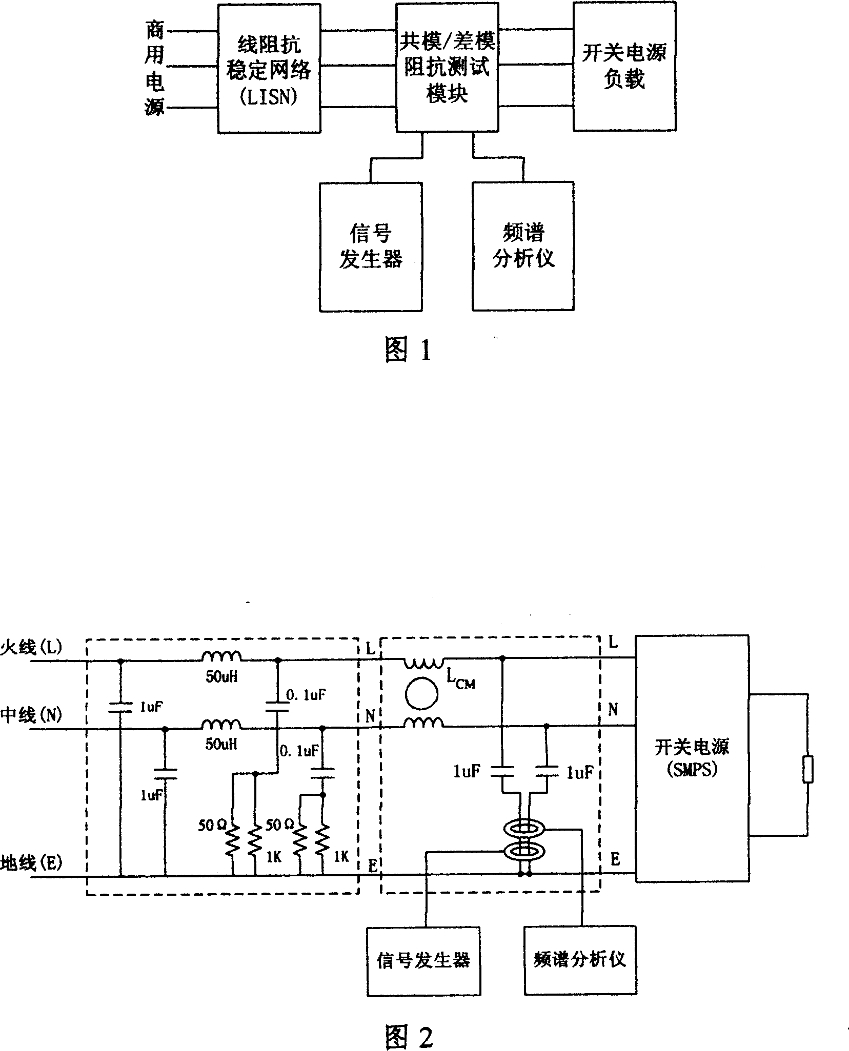
[0024] As shown in Figures 1 and 2, the internal impedance measurement device of the EMI noise source of the switching power supply is composed of a line impedance stabilization network (LISN), a common mode impedance test module, a switching power supply (SMPS) and a load, a signal generator and a spectrum analyzer. The power line from the power grid is directly input into the line impedance stabilization network (LISN), passes through the common mode impedance measurement module, and then is input into the switching power supply and load to form a whole power loop. The signal generator provides an input signal for the common mode impedance test module, and then the response signal in the module is detected by the spectrum analyzer.
[0025] The common mode impedance test module consists of a pair of 16mH common mode choke coils, two 1uF capacitors and two current probes, one of which is an injection current probe, choose Tektronix CT2, and one is a detection current probe, ch...
Embodiment 2
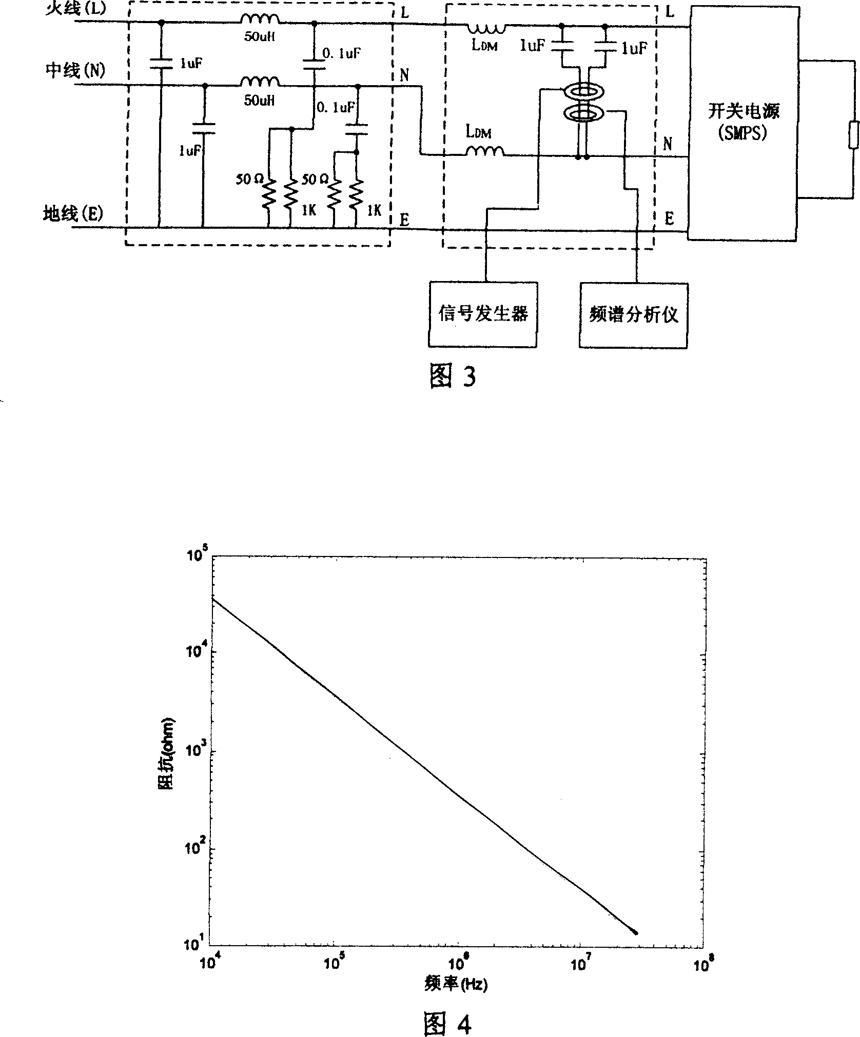
[0029] As shown in Figures 1 and 3, the internal impedance measurement device of EMI noise source of switching power supply is composed of line impedance stabilization network (LISN), differential mode impedance test module, switching power supply (SMPS) and load, signal generator and spectrum analyzer. The power line from the power grid is directly input to the line impedance stabilization network (the line impedance stabilization network adopts an international standard structure), passes through the differential mode impedance measurement module, and then is input to the switching power supply and load to form a whole power supply circuit. The signal generator provides an input signal for the common mode impedance test module, and then the response signal in the module is detected by the spectrum analyzer.
[0030] The differential mode impedance test module consists of two 350uH differential mode choke coils, two 1uF capacitors and two current probes. The power lines L, N,...
Embodiment 3
[0032] Taking the Keri switching power supply as an example, the test is carried out. The experimental device is shown in Figure 1. The test is carried out when the circuit is connected to the standard impedance, short circuit and normal operation of the switching power supply. For the test of the internal impedance of the noise source of the switching power supply, the main points are: Common mode and differential mode are tested. Except for the difference in the impedance test module, the test methods and steps are the same.
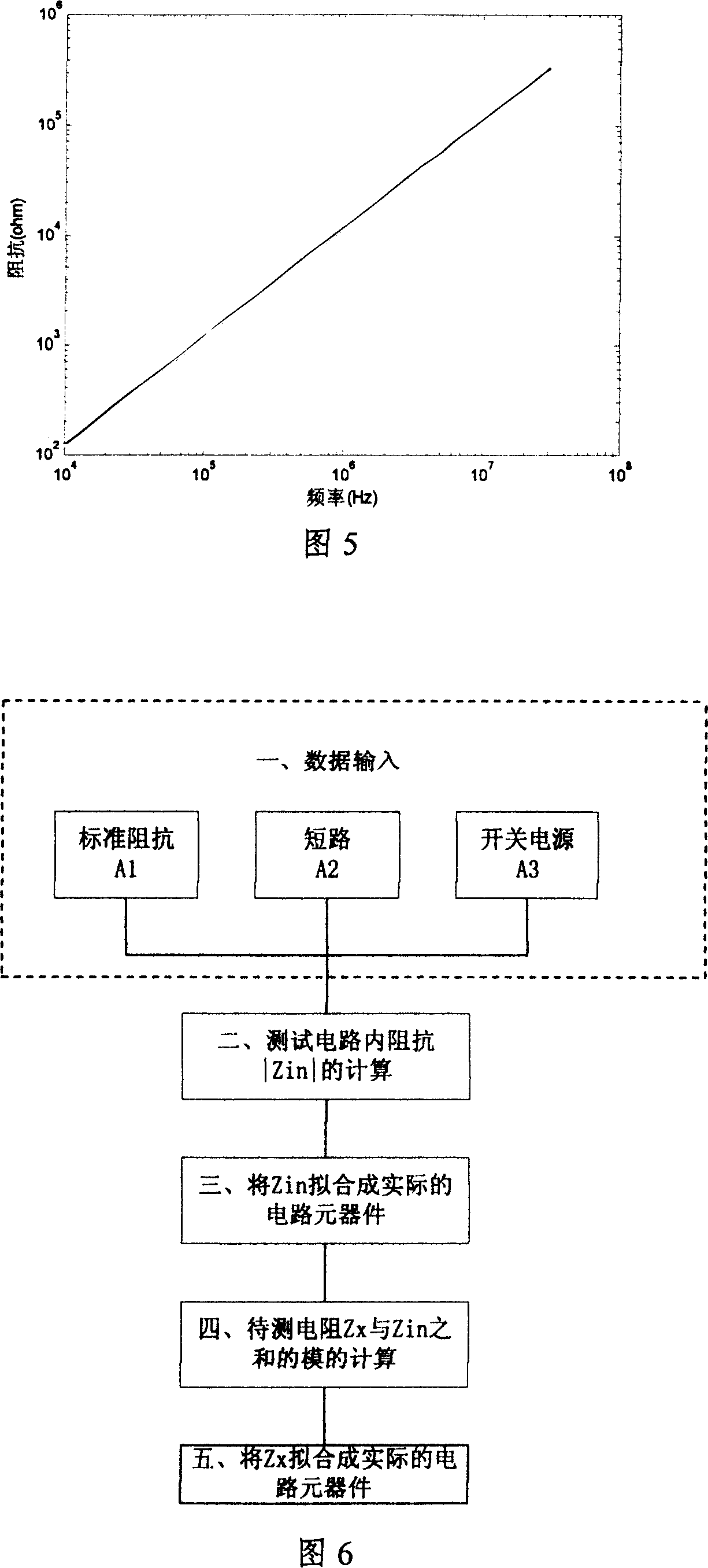
[0033] Step 1: First remove the SMPS from the main circuit, short the L and N wires, and connect a fixed impedance R std (Generally take 500Ω), one end of the impedance is connected to the short-circuit point of the L and N wires, and the other end is connected to the E wire. The neutral line impedance stabilization network of the main circuit is not energized, adjust the output frequency of the signal generator, take several points within the range of...
PUM
 Abstract
Description
Claims
Application Information
 - R&D
- Intellectual Property
- Life Sciences
- Materials
- Tech Scout
- Unparalleled Data Quality
- Higher Quality Content
- 60% Fewer Hallucinations
Browse by: Latest US Patents, China's latest patents, Technical Efficacy Thesaurus, Application Domain, Technology Topic, Popular Technical Reports.
© 2025 PatSnap. All rights reserved.Legal|Privacy policy|Modern Slavery Act Transparency Statement|Sitemap|About US| Contact US: help@patsnap.com


