System for measuring internal impedance of noise source of switching power supply EMI based on Hilbert transform and current probe, and measuration method
A technology of current probe and switching power supply, which is applied in the direction of measuring resistance/reactance/impedance, measuring devices, measuring electrical variables, etc. It can solve the problems of not knowing the internal interference source and impedance of the noise source, ignoring the internal impedance of the noise source, etc.
- Summary
- Abstract
- Description
- Claims
- Application Information
AI Technical Summary
Problems solved by technology
Method used
Image
Examples
Embodiment 1
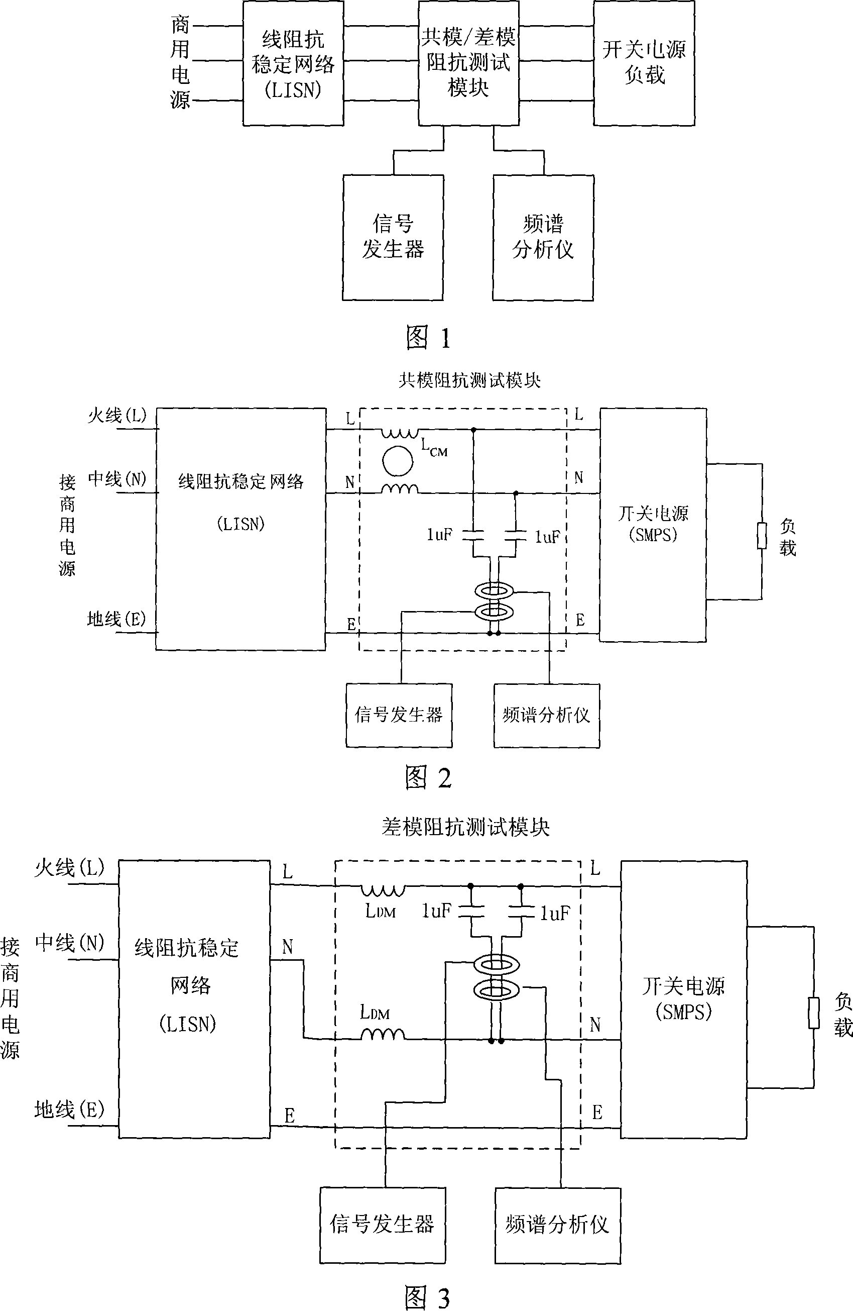
[0073] As shown in Figure 1 and Figure 2, the switching power supply EMI noise source internal impedance test system based on Hilbert transform and current probe is composed of line impedance stabilization network (LISN), common mode impedance test module, signal generator and spectrum analyzer; The power line from the power grid is directly input into the line impedance stabilization network (LISN), through the common mode impedance measurement module, and then input into the switching power supply (SMPS) and the load to form a whole power circuit; the signal generator is a common mode impedance The test module provides an input signal, and then the response signal in the module is detected by the spectrum analyzer.
[0074] In the power circuit, the function of the line impedance stabilization network (LISN) is to provide power for the switching power supply, and at the same time isolate the noise on the power supply side from entering the test circuit, and also isolate the n...
Embodiment 2
[0077] As shown in Figure 1 and Figure 3, the switching power supply EMI noise source internal impedance test system based on Hilbert transform and current probe is composed of line impedance stabilization network (LISN), differential mode impedance test module, signal generator and spectrum analyzer; The power line from the power grid is directly input into the line impedance stabilization network (LISN), through the differential mode impedance measurement module, and then input into the switching power supply (SMPS) and the load to form a whole power loop; the signal generator is a differential mode impedance The test module provides an input signal, and then the response signal in the module is detected by the spectrum analyzer. In the power loop, the differential mode impedance test module is used to measure the internal impedance of the switching power supply.
[0078] The differential mode impedance test module is composed of two differential mode choke coils, two capaci...
Embodiment 3
[0080] Taking a commercial switching power supply as an example, the test is carried out. The experimental device is shown in Figure 1. The test is carried out when the circuit is connected to the standard impedance, short circuit and normal operation of the switching power supply. For the test of the internal impedance of the noise source of the switching power supply, the main points are: Common mode and differential mode are tested. Except for the difference in the impedance test module, the test methods and steps are the same. Its determination steps are as follows:
[0081] Step 1: First remove the SMPS from the main circuit, short the L and N wires, and connect a fixed impedance R std , one end of the impedance is connected to the short-circuit point of the L and N wires, and the other end is connected to the E wire; the neutral impedance of the main circuit is stable and the network is not energized, adjust the output frequency of the signal generator, and take several ...
PUM
 Abstract
Description
Claims
Application Information
 - R&D
- Intellectual Property
- Life Sciences
- Materials
- Tech Scout
- Unparalleled Data Quality
- Higher Quality Content
- 60% Fewer Hallucinations
Browse by: Latest US Patents, China's latest patents, Technical Efficacy Thesaurus, Application Domain, Technology Topic, Popular Technical Reports.
© 2025 PatSnap. All rights reserved.Legal|Privacy policy|Modern Slavery Act Transparency Statement|Sitemap|About US| Contact US: help@patsnap.com


