
Display Device

a display device and display technology, applied in the direction of static indicating devices, coupling device connections, instruments, etc., can solve the problems of display device malfunction and display device defectiveness

Active Publication Date: 2008-04-03
SAMSUNG DISPLAY CO LTD
View PDF5 Cites 15 Cited by
  • Summary
  • Abstract
  • Description
  • Claims
  • Application Information

AI Technical Summary

Benefits of technology

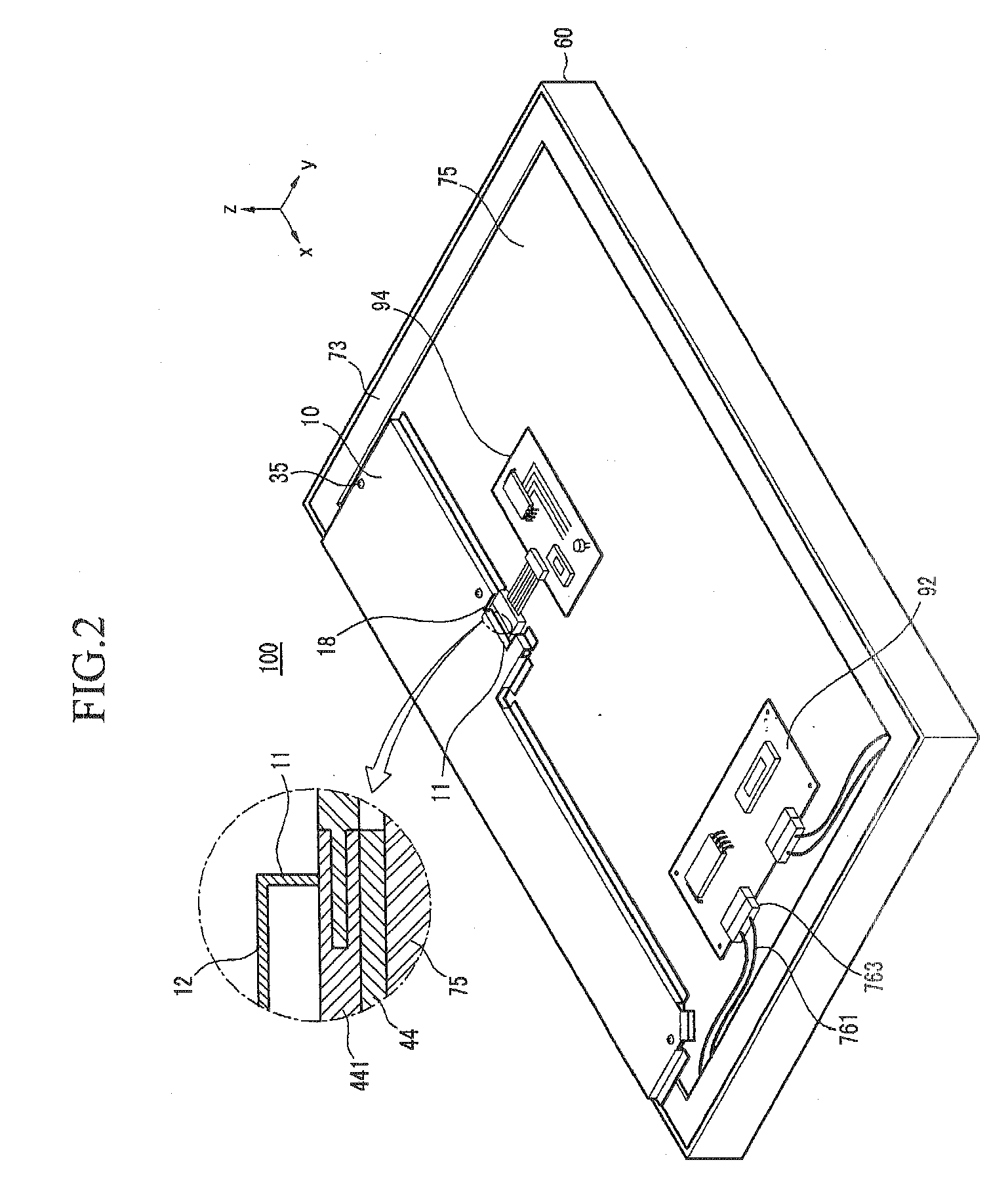
[0024]Accordingly, in an assembling process, the connector can be substantially prevented from being separated from the PCB and EMI generated from the connector can be effectively suppressed.

Problems solved by technology

Such a display device has a problem in that, during an assembly process thereof, a cable that is connected to the connector of the PCB may be separated from the PCB, resulting in a defective display device.
In addition, electromagnetic interference (EMI) generated from the connector of the PCB cannot be suppressed, causing a malfunction of the display device.

Method used


Image

  • Display Device
  • Display Device
  • Display Device

Examples


Embodiment Construction

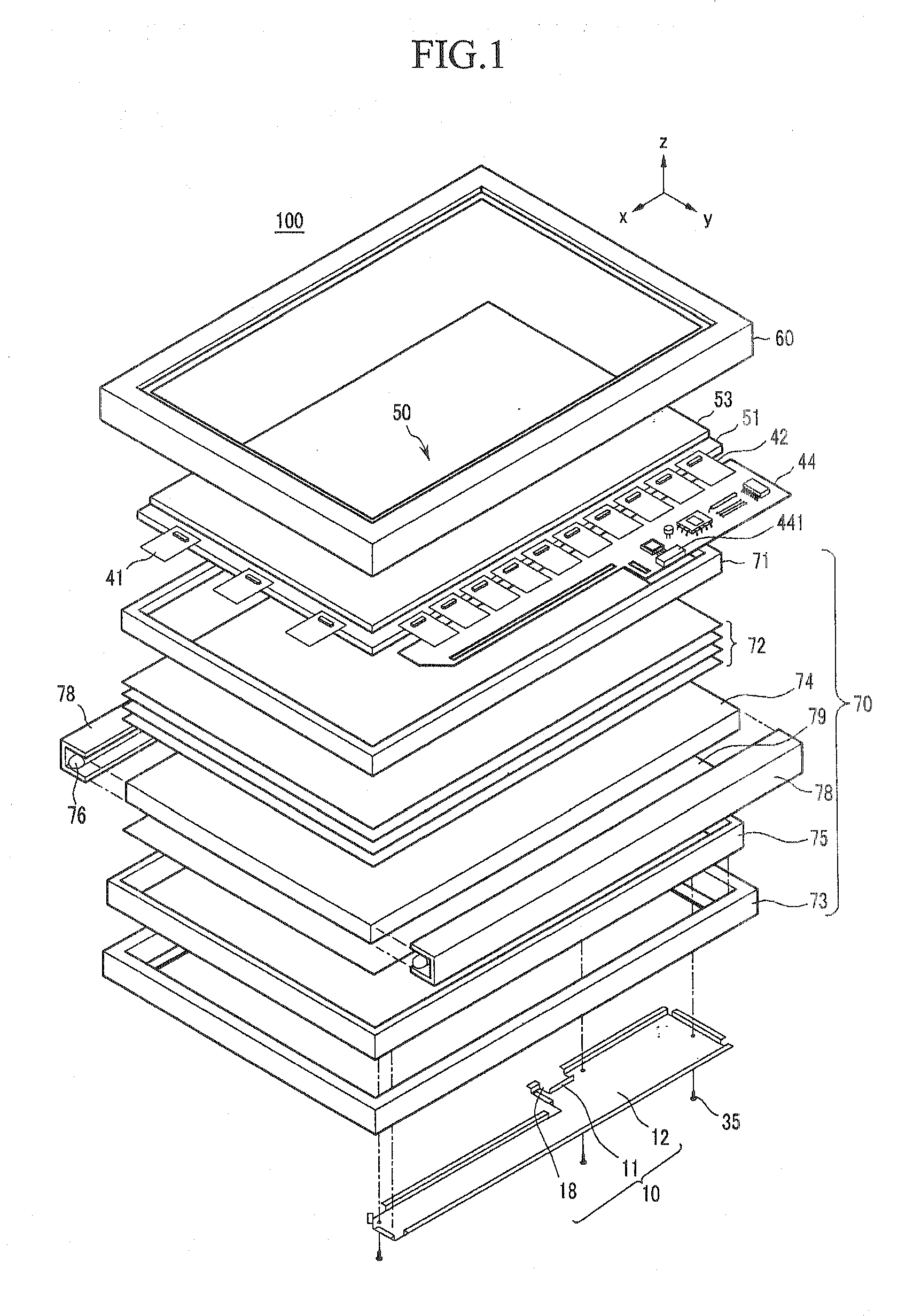
[0032]A display device according to exemplary embodiments of the present invention will now be described with reference to the accompanying drawings. A liquid crystal display panel is illustrated as an embodiment of a panel assembly employed for the display device in the accompanying drawings, which exemplifies and does not limit the present invention.

[0033]A display device having an edge type backlight assembly is illustrated as an embodiment of the present invention in the accompanying drawings, which exemplifies and does not limit the present invention.

[0034]In the drawings, the same reference numerals designate the same or like elements throughout the specification.

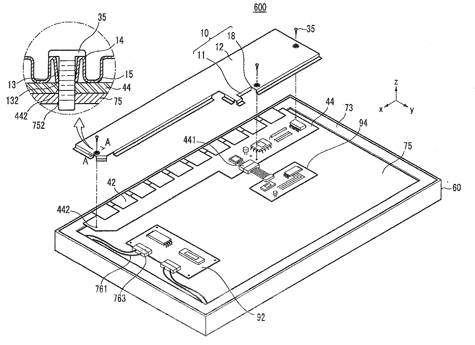
[0035]As shown in FIG. 1, according to an embodiment of the present invention, a display device 100 includes a backlight assembly 70 for providing light and a panel assembly 50 for displaying an image upon receiving light. The display device 100 additionally includes a front support member 60 for fixedly supporting th...


PUM

PropertyMeasurementUnit
structureaaaaaaaaaa
weightaaaaaaaaaa
sizeaaaaaaaaaa

Abstract

A display device includes a panel assembly for forming an image, a printed circuit board (PCB) connected with the panel assembly and having a connector; a support member for supporting the panel assembly and having the PCB installed on a rear surface thereof, and a cover member combined with the support member, covering the PCB, and having an opening exposing the connector. A fixing part formed at the opening of the cover member fixes the connector to the PCB.

Description

CROSS-REFERENCE TO RELATED APPLICATION[0001]This application is a Continuation Application from a U.S. patent application Ser. No. 11 / 529,034 filed Sep. 28, 2006, the entire contents of which are incorporated herein by reference.BACKGROUND OF THE INVENTION[0002](a) Field of the Invention[0003]The present invention relates to a display device, and more particularly, to a display device with a structure of a cover member that covers a printed circuit board (PCB) providing a drive signal to a panel assembly.[0004](b) Description of Related Art[0005]As semiconductor technologies have advanced, display devices, such as liquid crystal displays (LCD), have been developed to be small and light weight with high performance.[0006]Given the size, weight, and performance, e.g., low power consumption, characteristics of LCDs, LCDs have been increasingly used as a substitute for conventional cathode ray tubes (CRT).[0007]In light-receiving (non-emissive) LCD display devices, a voltage is applied ...

Claims


Application Information

Patent Timeline
Patent Type & Authority Applications(United States)
IPC IPC(8): G02F1/133H01R12/16
CPCH01R23/6873G02F1/13452H01R13/6595H01R12/00
Inventor PARK, HYOUNG-JUN
Owner SAMSUNG DISPLAY CO LTD
Learn More