
Hybrid substrate and method for fabricating the same

a technology of hybrid substrates and substrates, applied in the field of hybrid substrates, can solve the problems of not providing for hybrid substrate fabrication, art wafer bonding techniques, etc., and achieve the effects of reducing the inductive noise caused by the wide metal wiring, and reducing the size of the system

Inactive Publication Date: 2005-12-22
IBM CORP
View PDF11 Cites 0 Cited by
  • Summary
  • Abstract
  • Description
  • Claims
  • Application Information

AI Technical Summary

Benefits of technology

[0011] Finally, another aspect of the present invention is to provide a hybrid substrate configured for patterning interconnects thereon for interconnecting different devices fabricated on the hybrid substrate. This would greatly reduce the size of a system fabricated on the hybrid substrate, since the patterned interconnects would eliminate contact pads, and wide metal wirings used in prior art systems. Further, inductive noise caused by the wide metal wirings would also be reduced.

Problems solved by technology

The prior art wafer bonding techniques, however, do not provide for fabricating a hybrid substrate by integrating three or more different types of material on a common carrier substrate.

Method used


Image

  • Hybrid substrate and method for fabricating the same
  • Hybrid substrate and method for fabricating the same
  • Hybrid substrate and method for fabricating the same

Examples


Embodiment Construction

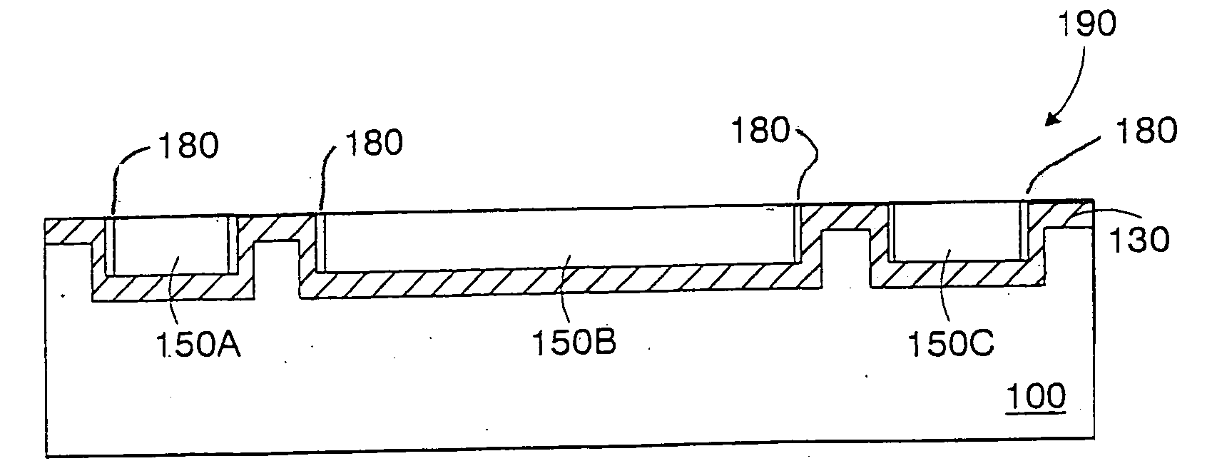
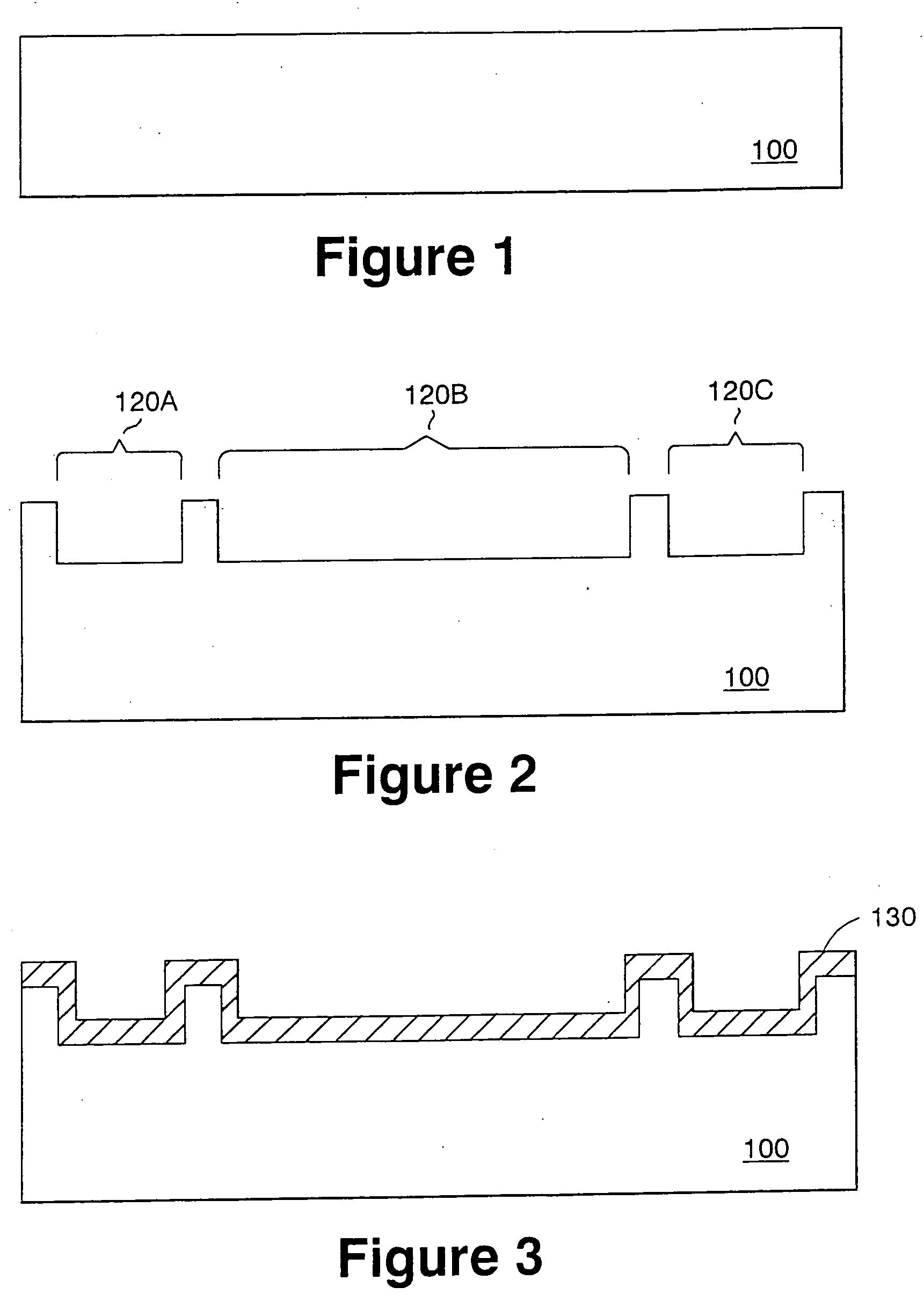
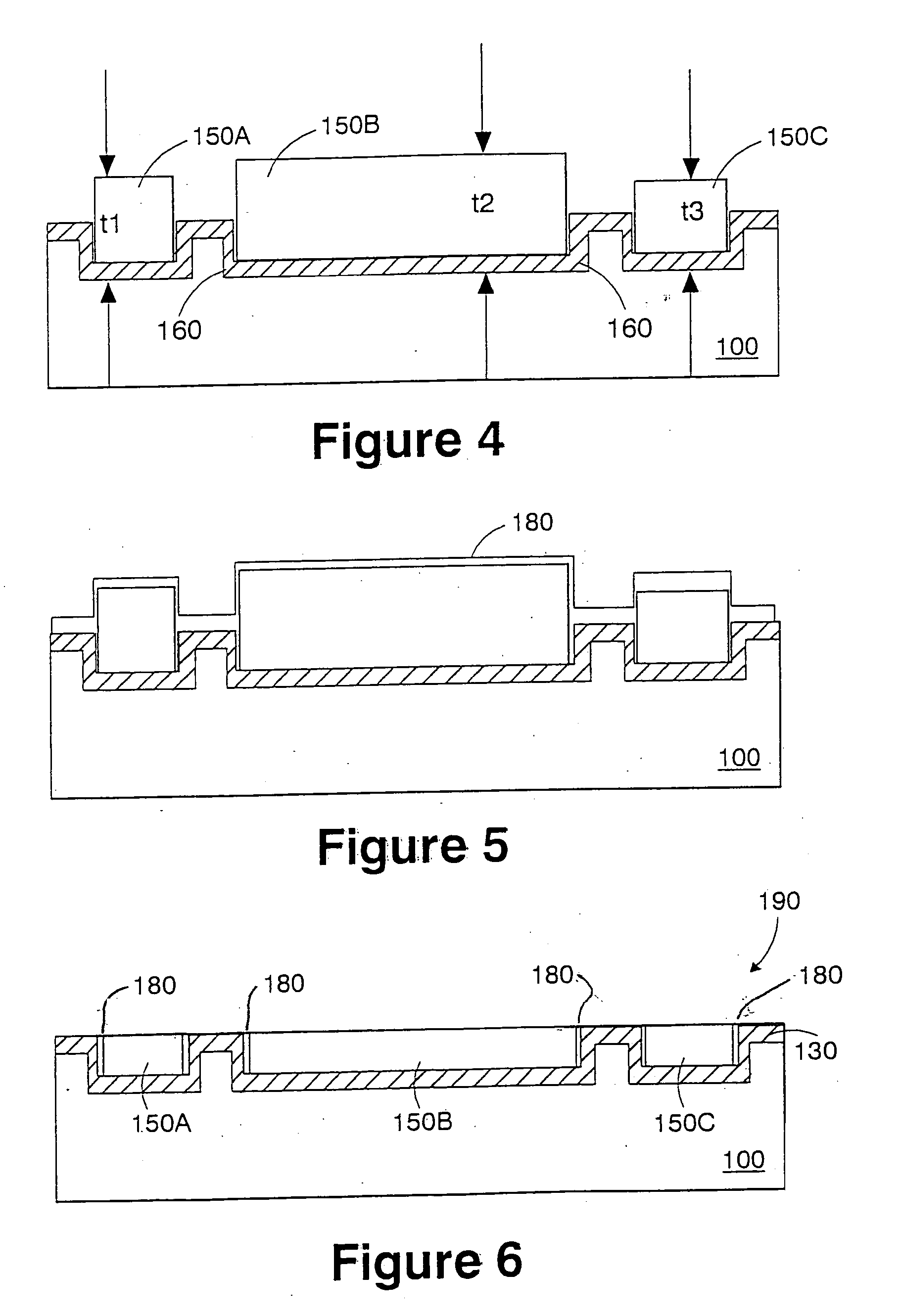
[0016] The present invention provides a hybrid substrate, i.e., a substrate fabricated from different materials, and method for fabricating the same. The hybrid substrate is configured for fabricating more than two different devices thereon, has a high thermal conductivity, and is configured for patterning interconnects thereon for interconnecting the different devices fabricated on the hybrid substrate.

[0017]FIG. 1 is a cross-sectional view of a portion of a carrier substrate 100 for fabricating the hybrid substrate according to the present invention. The carrier substrate 100 is preferably fabricated from aluminum nitride (AlN). AlN is a desirable substrate for the carrier substrate 100 due to its ability to support a wide variety of materials provided thereon due to its high thermal conductivity. Other preferred materials for the carrier substrate 100 include quartz, glass, ceramic, CVD diamond, and sapphire.

[0018] A description of the preferred method for fabricating the hybri...


PUM

PropertyMeasurementUnit
depthaaaaaaaaaa
thicknessaaaaaaaaaa
thermal conductivityaaaaaaaaaa

Abstract

A hybrid substrate, i.e., a substrate fabricated from different materials, and method for fabricating the same are presented. The hybrid substrate is configured for fabricating more than two different devices thereon, has a high thermal conductivity, and is configured for patterning interconnects thereon for interconnecting the different devices fabricated on the hybrid substrate.

Description

FIELD OF THE INVENTION [0001] This invention relates to the field of integrated circuit (IC) design. Specifically, it relates to a hybrid substrate and method for fabricating the same. BACKGROUND OF THE INVENTION [0002] Wafer bonding (also called wafer fusion) techniques have been extensively practiced for different applications requiring different substrates. These techniques enable two different wafers to be bonded together, so that fabrication of highly lattice-mismatched and orientation-mismatched heterostructures become possible without generating threading dislocations. For example, wafer bonding techniques have been utilized to form silicon-on-oxide (SOI) substrate, and for bonding III-V materials with other materials. [0003] The prior art wafer bonding techniques, however, do not provide for fabricating a hybrid substrate by integrating three or more different types of material on a common carrier substrate. It is desirable to have a system chip which includes mixed devices,...

Claims


Application Information

Patent Timeline
Patent Type & Authority Applications(United States)
IPC IPC(8): H01L21/20H01L27/12
CPCH01L27/12H01L21/02381H01L21/02527H01L21/0243Y10T428/24355Y10T428/24802Y10T428/24942Y10T428/30Y10T428/12674
Inventor HSU, LOUIS L.WANG, LI-KONG
Owner IBM CORP
Learn More