Ultra-low profile vehicular antenna methods and systems

Inactive Publication Date: 2005-12-22
MICRO ANT
View PDF9 Cites 5 Cited by
  • Summary
  • Abstract
  • Description
  • Claims
  • Application Information

AI Technical Summary

Benefits of technology

[0013] In an embodiment this invention may provide for mounting the LNA above the modular patch antenna while maintaining compliance with gain requirements for a SDARS antenna. With the LNA mounted above the modular patch antenna the overall profile of the antenna is much lower than in the conventional design. In such embodiments a coax cable may be required to connect to the LNA from the top of the antenna assembly. In an embodiment the coax cable may be routed from the top of the LNA through a hole that may be near the center of the modular patch antenna and out the bottom of the antenna assembly. This configuration may have the LNA offset from the center of the modular patch antenna to allow for an advantageous connection location for the LNA and the modular patch antenna using the coax cable center wire. In an embodiment the resulting antenna assembly with the LNA mounted on the top of the modular patch antenna may provide for efficient use of space and may result in an ultra-low profile antenna under 0.350 inches tall with a radome diameter of approximately 2 inches. The shape of the radome may be round, square, multi-sided polygon, or other shape that covers the antenna assembly.

Problems solved by technology

The LNA needs proper shielding for high performance operation and therefore may require extra space between the LNA and the modular patch antenna.
With the covering radome, this design may result in a significantly large assembly that may not be preferred by some users.

Method used


Image

  • Ultra-low profile vehicular antenna methods and systems
  • Ultra-low profile vehicular antenna methods and systems
  • Ultra-low profile vehicular antenna methods and systems

Examples


Embodiment Construction

[0019] Referring to FIG. 1, an embodiment of a typical construction of a SDARS antenna is shown. To provide a clear view of the sky a modular patch antenna 102 may be mounted on top of a LNA 108 with a coax cable 104 connecting the modular patch antenna 102 and the LNA 104 from below the assembly. This configuration may allow for an unobstructed view of the sky for the modular patch antenna 102 to receive transmissions, but this construction may also provide a significant height. The LNA may require shielding to prevent interference signals. The shielding may require extra spacing between the modular patch antenna and the LNA. The combined height of the modular patch antenna, LNA and shielding may require a large covering radome that may not be aesthetically pleasing to the user.

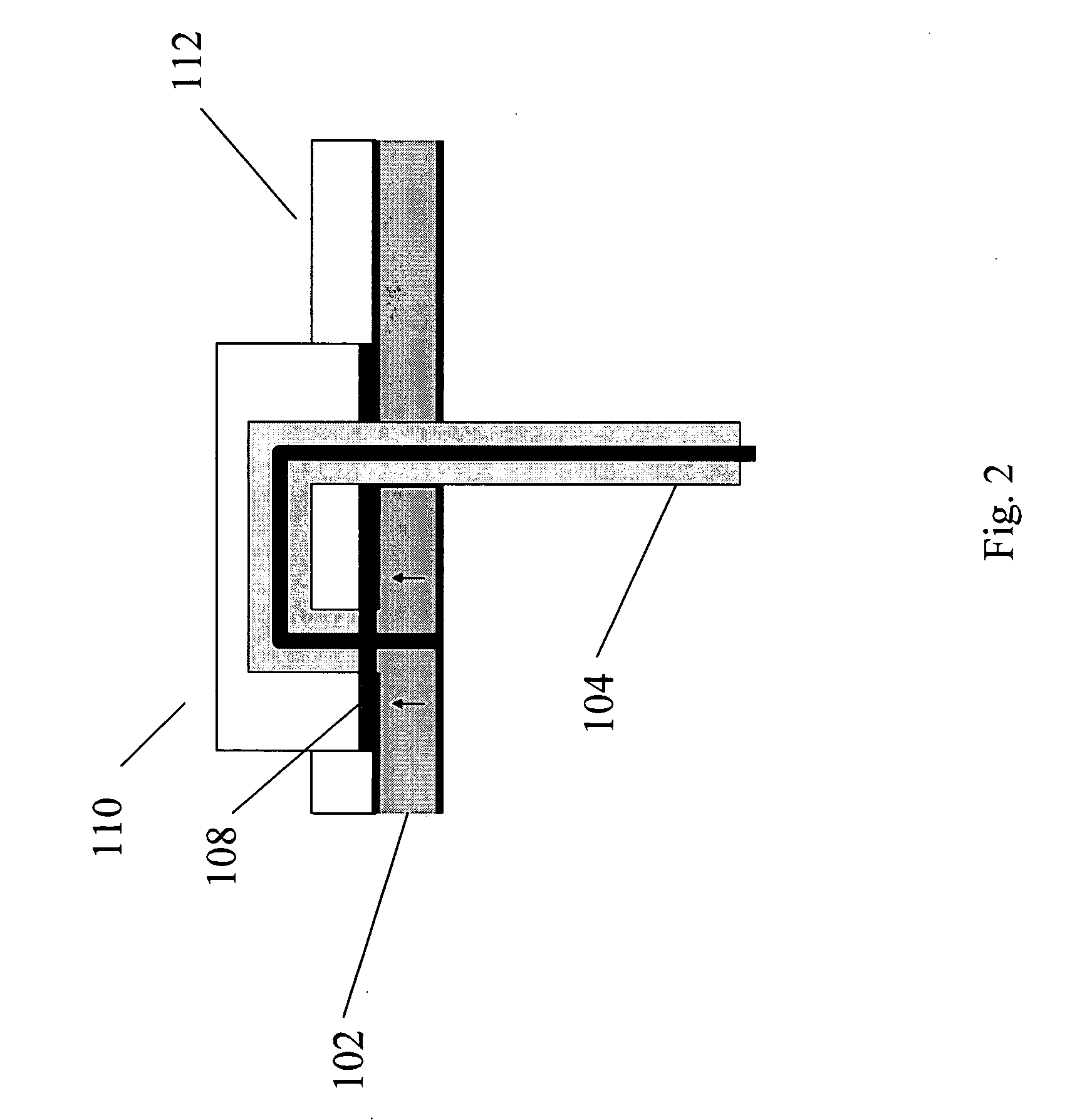
[0020]FIG. 2 shows a simplified embodiment of the ultra-low profile antenna. An LNA 108 may be mounted on top of the modular patch antenna 102 and may utilize the available volume of the antenna assembly mo...


PUM


Abstract

A method and system of providing an antenna for a communication system is provided that has a LNA mounted above the modular patch antenna. The resulting SDARS antenna has an ultra-low profile providing a more acceptable size for the user while maintaining the antenna gain requirements.

Description

RELATED APPLICATIONS [0001] This application is a continuation-in-part of U.S. application Ser. No. 11 / 106,018, filed Apr. 14, 2005 and entitled “Low-Profile Unbalanced Vehicular Antenna Methods and Systems,” which claimed the benefit of U.S. Prov. App. No. 60 / 562,857, filed Apr. 16, 2004.[0002] This application also claims the benefit of U.S. Prov. App. No. 60 / 571,725, filed May 17, 2004 and entitled “Ultra-Low Profile Vehicular Antenna Methods and Systems.”[0003] Each of the above-referenced applications is incorporated herein by reference in its entirety. BACKGROUND [0004] 1. Field [0005] This invention relates to the methods and systems for a modular patch antenna and more particularly, embodiments of the present invention relate to the field of providing an ultra-low profile antenna for satellite radio transmissions. [0006] 2. Description of the Related Art [0007] Satellite Digital Audio Radio Services (SDARS) antennas receive satellite and terrestrial transmissions and are typ...

Claims


Application Information

Patent Timeline
IPC IPC(8): H01Q1/38H01Q9/04H01Q13/10H01Q23/00
CPCH01Q1/38H01Q23/00H01Q13/10H01Q9/0464
Inventor POE, GREGORYHALLER, NICK
Owner MICRO ANT
Why Eureka
Try Eureka