
Tubular sputtering targets and methods of flowforming the same

Inactive Publication Date: 2005-12-22
DYNAMIC FLOWFORM +1
View PDF13 Cites 80 Cited by
  • Summary
  • Abstract
  • Description
  • Claims
  • Application Information

AI Technical Summary

Benefits of technology

[0011] The methods of this invention simplify the production of sputtering target tubes. These methods reduce or eliminate the production of waste metal and / or the need to recycle such waste metals, thereby resulting in more efficient sputtering target production, which results in reduced production costs and / or ultimately cheaper sputtering target tubes. The methods of this invention can produce, and the targets of this invention can have, increased biaxial strength. Also, the targets of this invention have a finer, more uniform radial grain structure than sputtering targets produced by prior art methods, which results in a more uniform and / or consistent sputtering action.

Problems solved by technology

Current methods of forming sputtering target tubes are generally inefficient, with large portions of the valuable metal being machined away to form the tube.
The metal that is machined from the cylinder can occasionally be recycled, however, machining and recycling necessitate additional steps that add to the costs and complexity of the target production process.

Method used


Image

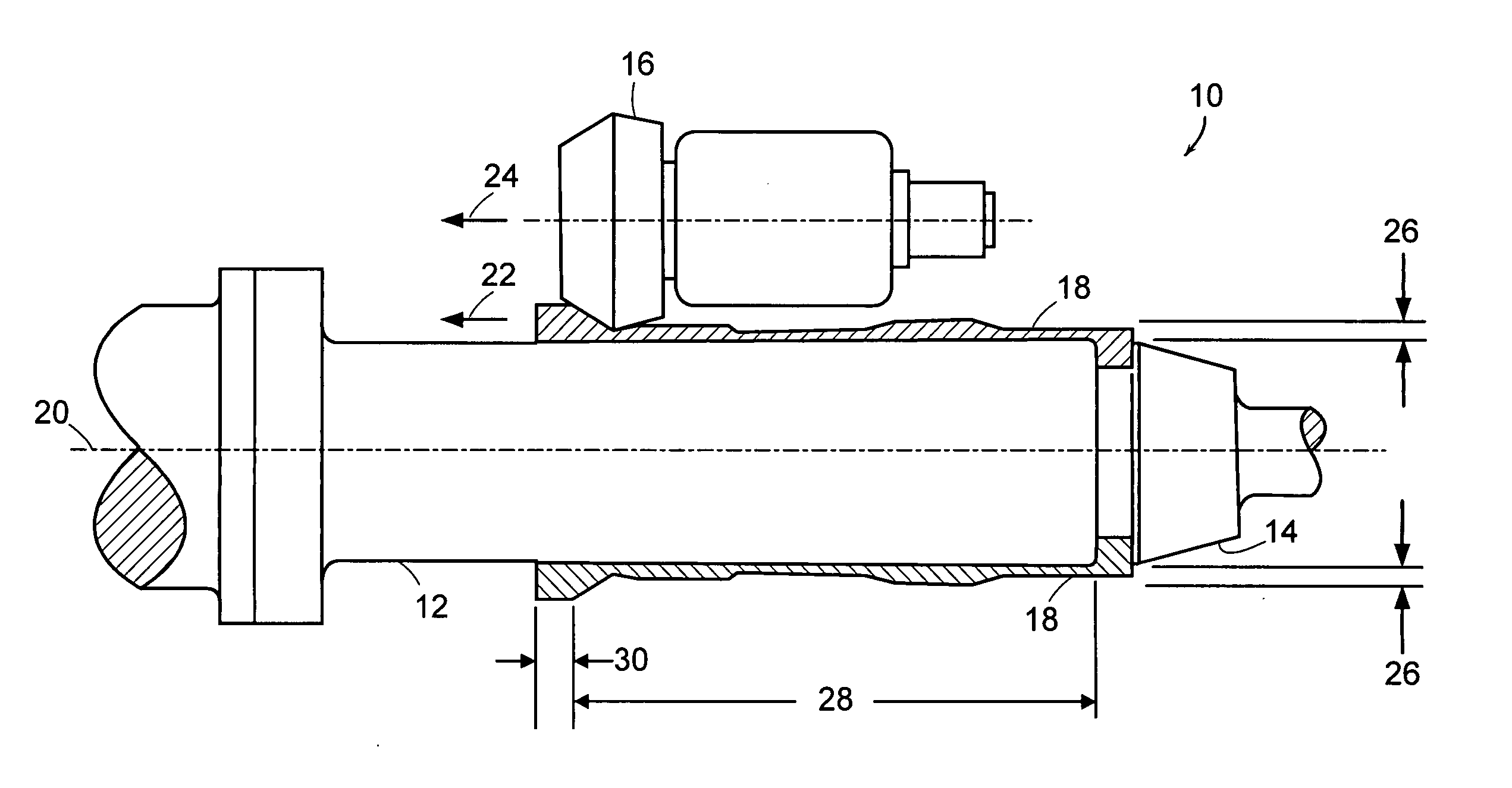
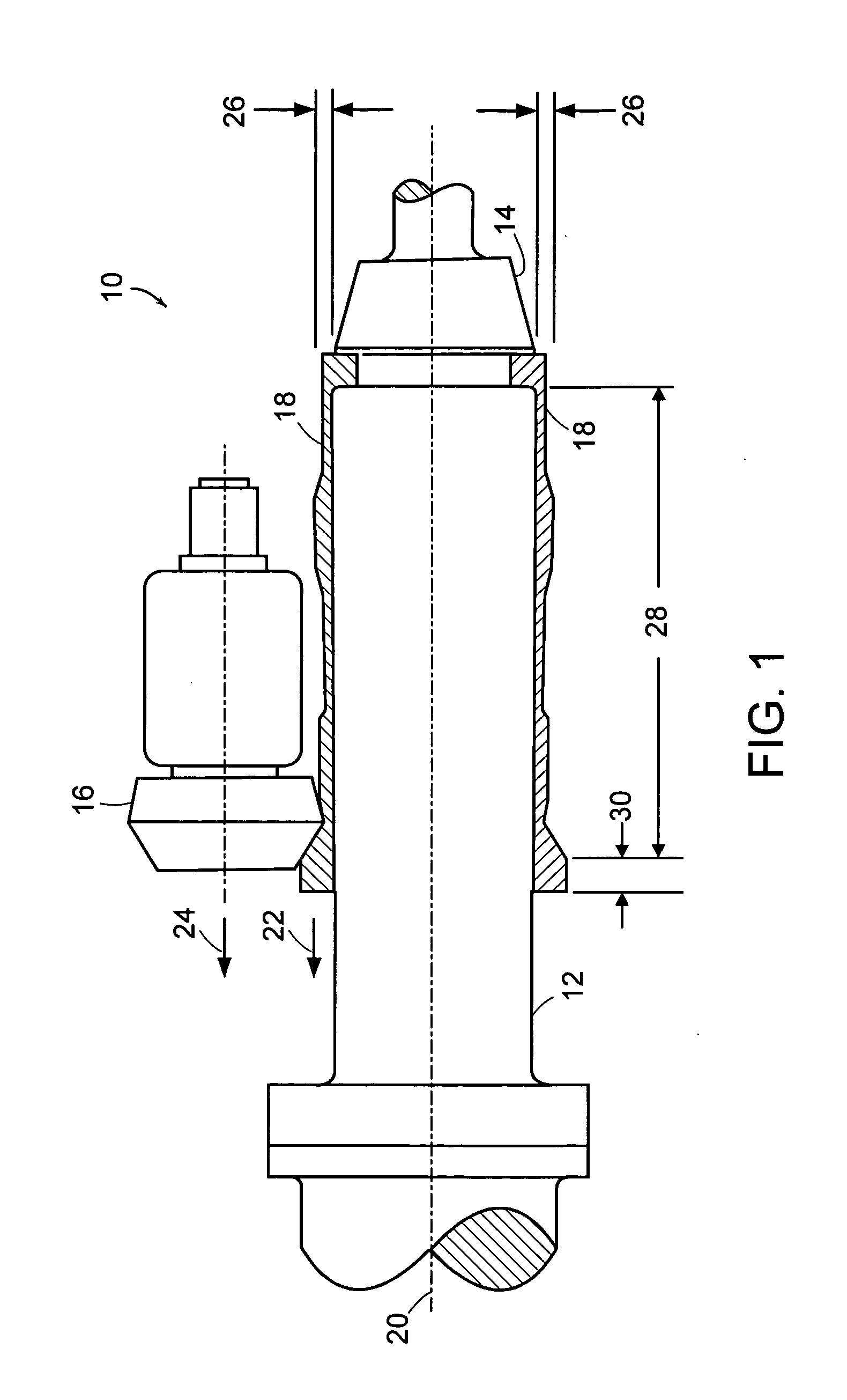
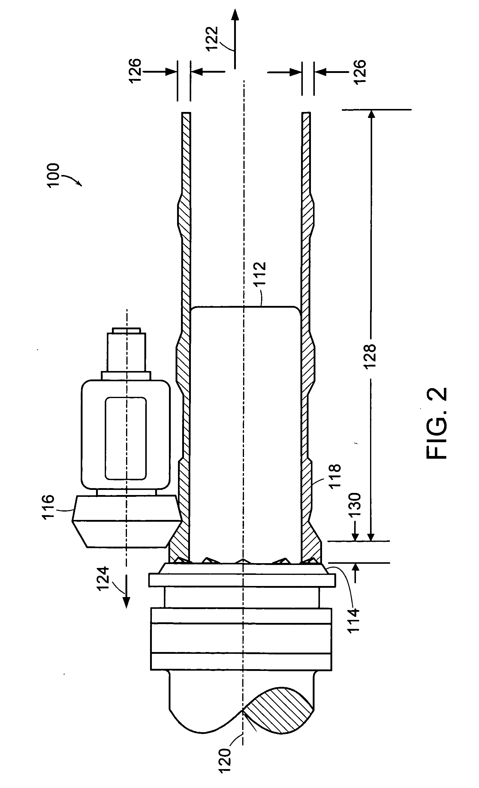
  • Tubular sputtering targets and methods of flowforming the same
  • Tubular sputtering targets and methods of flowforming the same
  • Tubular sputtering targets and methods of flowforming the same

Examples


example

Metallurgical Comparison

[0067] A metallurgical evaluation of two samples of commercially pure titanium grade 2 (“CP2”) tubing material was conducted. The first sample was taken from a metal hollow preform that was formed via an extrusion process. The second sample was taken from a sputtering target tube formed by flowforming a metal hollow preform that had been formed via an extrusion process.

[0068] The grain structure of the two samples was determined through preparation of metallographic cross sections in the three orientations described above, namely a longitudinal orientation, a radial orientation, and a circumferential orientation.

[0069] The metallurgical microstructure was documented by photographing the etched cross sections at 500× magnification. The microphotographs in each orientation were combined to create a simulated three-dimensional view of the grain structure in the three orientations. The 500× magnification of the microstructure of material of the first sample (i...


PUM

PropertyMeasurementUnit
Lengthaaaaaaaaaa
Fractionaaaaaaaaaa
Thicknessaaaaaaaaaa

Abstract

Described herein are sputtering target tubes and methods of making sputtering target tubes. The methods include a step of forming a metal hollow preform and flowforming the metal hollow preform to form a sputtering target tube. The step of forming a metal hollow preform can include such processes as extrusion, hot isostatic pressing of a metal powder, rotary-piercing, casting, machining a billet, and plasma spray-forming. In some embodiments, the tubular sputter targets have a variable wall-thickness.

Description

RELATED APPLICATIONS [0001] This application is a continuation-in-part of U.S. application Ser. No. 11 / 004,622, filed Dec. 3, 2004, which claims the benefit of U.S. Provisional Application No. 60 / 580,472 filed on Jun. 16, 2004, and 60 / 605,489 filed on Aug. 30, 2004. The entire teachings of the above applications are incorporated herein by reference.BACKGROUND OF THE INVENTION [0002] Cathode sputtering processes are widely used for depositing thin coatings or films of material onto substrates. Such a process takes place in an evacuated chamber containing a small quantity of an ionizable gas (e.g., argon). Electrons emitted from a source held within the chamber ionize the gas to form a plasma and the ions produced bombard a target comprising the material to be sputtered, thereby causing atoms of the target material to be dislodged and subsequently deposited as a film on the substrate being coated. [0003] In a magnetron apparatus the rate of deposition may be increased by the use of ma...

Claims


Application Information

Patent Timeline
IPC IPC(8): C23C14/34
CPCC23C14/3414H01J37/3491H01J37/3423
Inventor FONTE, MATTHEW V.
Owner DYNAMIC FLOWFORM
Learn More