Method and device for controlling the current in a spark plug

a technology of spark plug and current control, which is applied in the direction of engine ignition, electrical equipment, other installations, etc., can solve the problems of increased consumption of electrical energy, increased wear of spark plugs, and difficulty in ignition of fuel mixtures

Active Publication Date: 2005-12-22
ALTRONIC
View PDF8 Cites 19 Cited by
  • Summary
  • Abstract
  • Description
  • Claims
  • Application Information

AI Technical Summary

Problems solved by technology

The drawback of this procedure is that the point of time for ignition of the fuel and air mixture can vary from cycle to cycle, which results in cycle to cycle variations of the torque delivered by the cylinder, from one combustion cycle to another.
At a high EGR, the concentration of inert gases is higher in the cylinder, whereby ignition of the fuel mixture can be more difficult, and in which case it may be of interest to have a more intense spark with a larger energy content.
A more intense spark may however give rise to an increased wear of the spark plug, as well as an increased consumption of electrical energy, which means that it is not desired without cause to have a too intense spark or a spark of too long duration.
Furthermore, in case the engine runs on very high speed, it may be unnecessary for the spark to have a very long duration, as the purpose of the spark is only to start the combustion in the cylinder.
When the spark over the plug disappears, there is a strong increase in the impedance between the electrodes of the spark plug, resulting in self-oscillation in the secondary circuit of the ignition coil, of which circuit the spark plug forms part.
Accordingly, it is evident that costly and complex equipment is required, for example in the form of a 40 kV high-voltage diode (alternatively an ignition coil having a saturatable core).
Also, this device will not really make it easy to control neither the spark current nor its duration.
In common for these to last mentioned methods is the drawback that the energy is supplied to the high-voltage side of the ignition coil, which is more complicated than if the energy is supplied to the low-voltage side of the ignition coil.
All methods mentioned above disclose the use of a high-voltage source in order to affect the spark current, which is a drawback from the point of view that a high voltage is relatively hard to achieve compared to a lower voltage.
Furthermore, non of the inventions discloses a method of achieving a spark for which it is easy to control the current intensity and duration in Arc Discharge Mode.
Accordingly, no real good method exists today for controlling the spark current in an ignition device, such as a spark plug in a combustion chamber.

Method used


Image

  • Method and device for controlling the current in a spark plug
  • Method and device for controlling the current in a spark plug
  • Method and device for controlling the current in a spark plug

Examples


Embodiment Construction

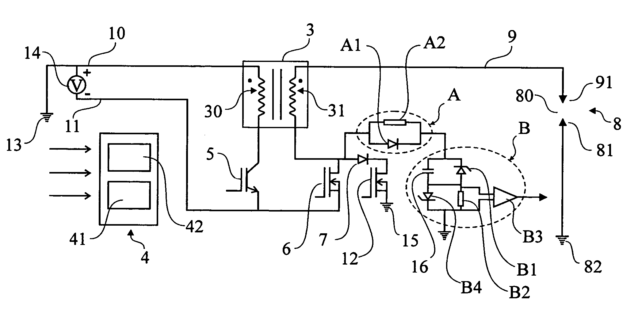
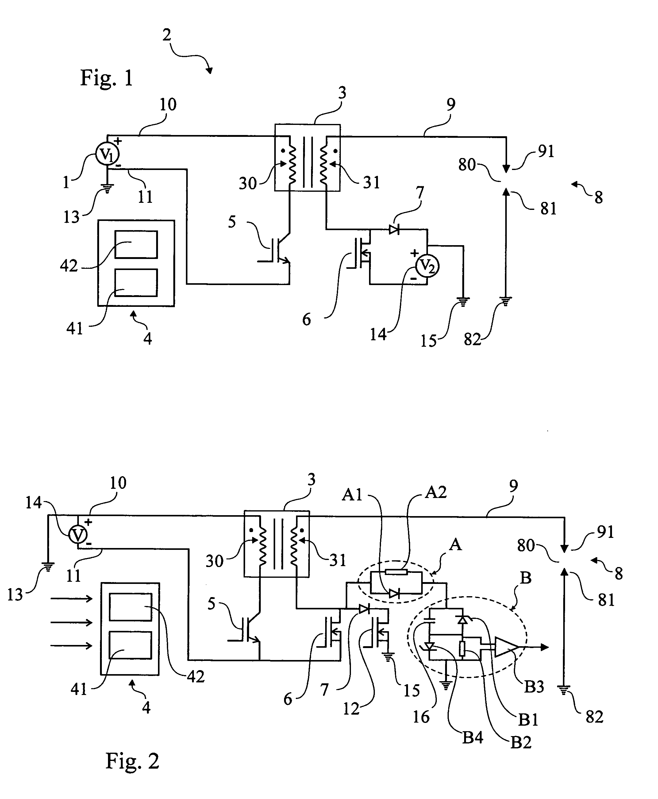
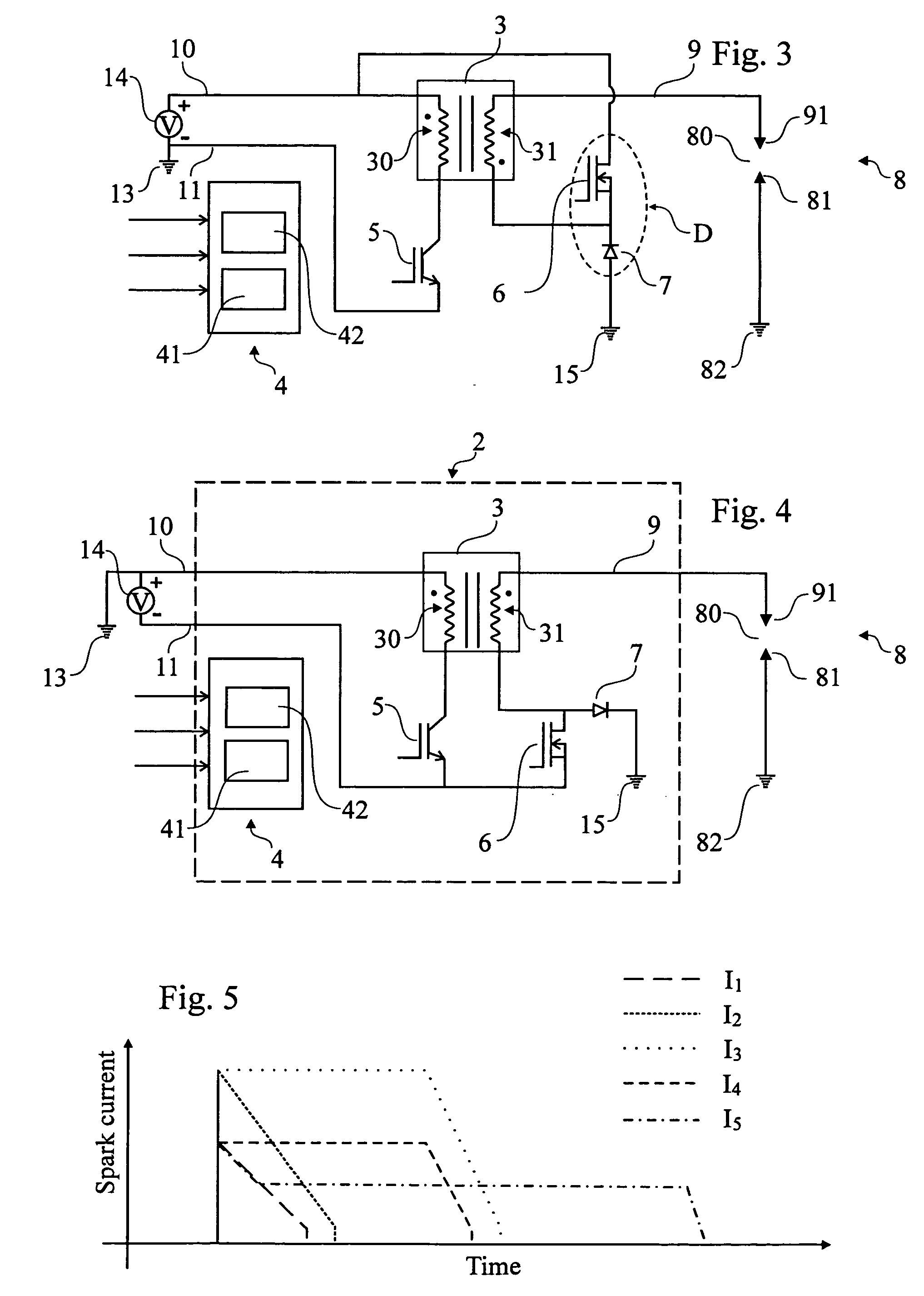
[0030]FIG. 1 shows a preferred embodiment of an ignition system according to the invention. It is shown that the ignition system, that is fed by voltage from a voltage source 1, such as a 12, 24 or 42 Volt battery, that is grounded 13. The positive pole 10 of the voltage source is connected to a first end of the primary coil 30 of an ignition coil 3. The negative pole 11 is connected to a first control unit 5, that is formed from a first transistor 5 connected to said negative pole 11 via the emitter. The collector of the first transistor 5 is connected to the other end of the primary coil 30 of the ignition coil 3, whereby a first circuit can be closed over the primary coil 30. This first circuit, called a primary circuit, is not different in circuit design from a conventional inductive ignition system.

[0031] In the following, the secondary circuit of the ignition system will be described, which secondary circuit differs in circuit design from a conventional inductive ignition sys...


PUM


Abstract

The present invention relates to a method of controlling the spark current in a spark plug (8), comprising a voltage source (1; 14), an ignition system (2) connected to the voltage source, and a spark plug (8) connected to the ignition system, which ignition system (2) comprises an ignition coil (3) and at least one regulating unit (5, 6) as well as a control unit (4), enabling control of the intensity and / or duration of the spark current, said ignition coil (3) comprising a secondary side (6, 31) arranged to be controlled in order to control the duration of the spark in Arc Discharge Mode. The invention also relates to an ignition device.

Description

TECHNICAL FIELD [0001] The present invention relates to a method of controlling the spark current in a spark plug, which spark plug is part of a ignition system, the method providing the possibility to control the intensity as well as the duration of the spark current, and thereby also the energy released by the spark. The invention also relates to a device for accomplishment of such control. PRIOR ART [0002] Many of the internal combustion engines of today make use of spark plugs to ignite a mixture of fuel and air. This takes place for example in the Otto engine, in which a premixed mixture of fuel and air is ignited. Spark plugs are also used in direct injection engines, in which fuel and air is mixed directly in the cylinder. Common fuels of today are different types of hydrocarbon compounds, such as petrol, alcohols and various gases such as natural gas and biogas. In the future, hydrogen gas may also be used. [0003] The function of the spark plug is mainly at a given point of ...

Claims


Application Information

Patent Timeline
Patent Type & Authority Applications(United States)
IPC IPC(8): F02P3/045F02P3/05
CPCF02P9/007F02P3/051F02P3/0453F02P3/0456H01T15/00
Inventor BILJENGA, BO
Owner ALTRONIC
Why Eureka
Try Eureka