
Strain gauge apparatus having a point-distributed sensor

a technology of point distribution and strain gauge, which is applied in the field of strain gauge, can solve the problems of deteriorating accuracy of measurement, resistance measured in high-order resonance mode, and not being a proper representative of the true mechanical strain at the center point of the strain gaug

Inactive Publication Date: 2005-12-22
LEE CHIH KUNG
View PDF2 Cites 22 Cited by
  • Summary
  • Abstract
  • Description
  • Claims
  • Application Information

AI Technical Summary

Benefits of technology

[0032] It is another object of the present invention to provide a strain gage apparatus that measures the true strain of an exact point of a MEMS device without having to using a small geometry to serve as a point sensor.
[0033] It is yet another object of the present invention to provide a strain gauge apparatus that measures the true strain of an exact point of a mechanical structure with high precision via removal of high-frequency noise vibrations sustained in the structure by self-filtering.

Problems solved by technology

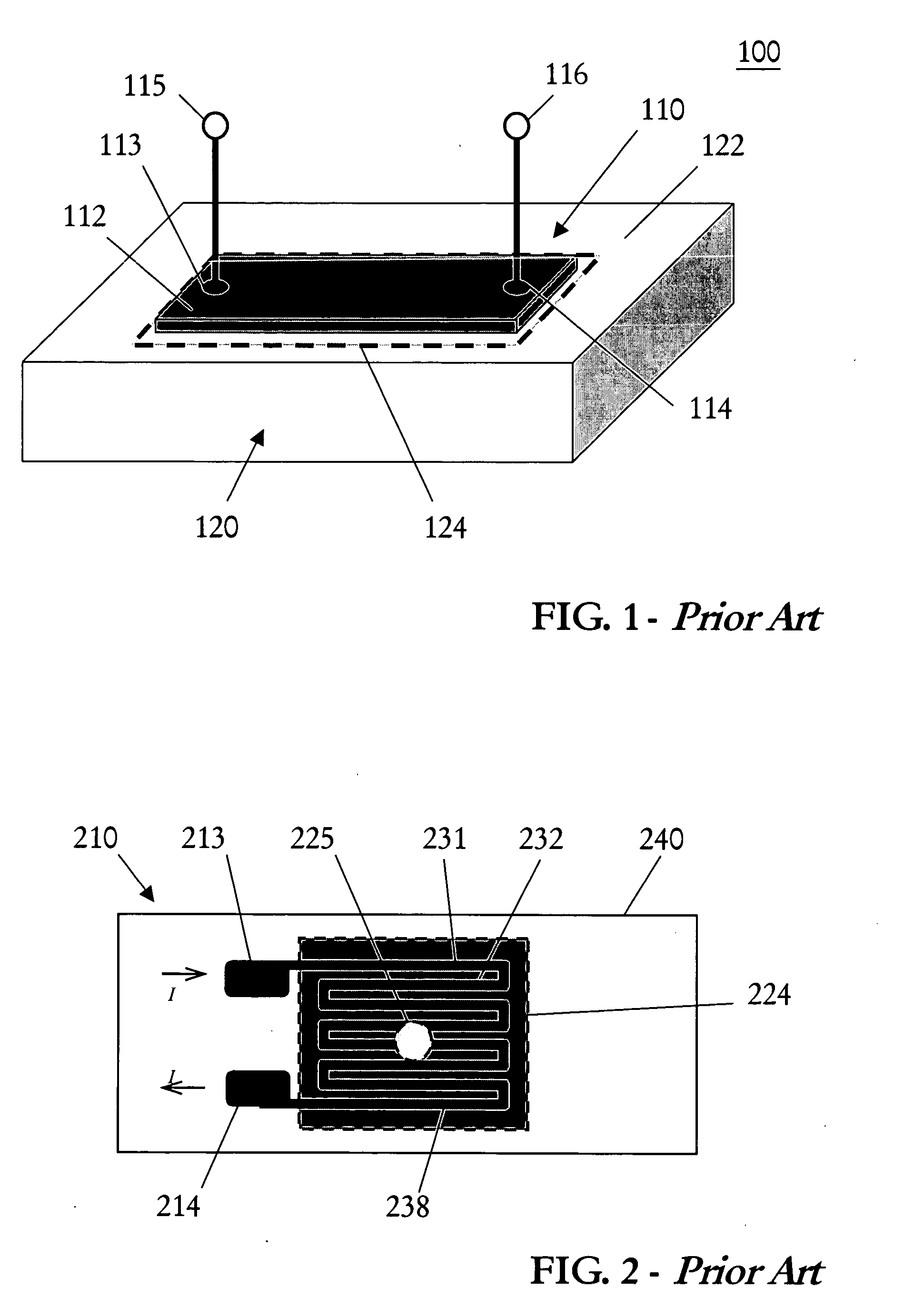
However, this typical resistance strain gauge is only capable of turning out an approximation of the actual strain information at the location generally identified by the dot-lined area 124 where it is deployed.
When the extent of strain variations is not sufficiently large compared to the size of the measuring sensor, accuracy of the measurement becomes deteriorated.
This problem is severe in systems with dynamic strain, since multiple wavelengths or frequencies may exist simultaneously in an excitation.
However, resistance measured in high-order resonance modes is no longer a proper representative of the true mechanical strain at the center point of the strain gauge.
However, there are at least a few serious problems that hinder the true usefulness of traditional resistance strain gauges.
Such aggregation information is only sufficient for an estimation of the true strain.
Limitation of lamina size, however, is directly translated into difficulties in resistance measurement for the part of instrumentation.
This limitation becomes even more acute when strain gage are used in MEMS devices.
This makes a strain gage in MEMS device hard to utilize.
First, because they are small in size, the available value of resistance cannot be large enough.
Second, in the applications of dynamic systems, the functions of strain gage will fail since it cannot be considered as a point sensor any more.
This limits the applications of strain gages in MEMS device.
Also, noise vibrations frequently sustained in a gauged mechanical structure interfere with the gauging.

Method used


Image

  • Strain gauge apparatus having a point-distributed sensor
  • Strain gauge apparatus having a point-distributed sensor
  • Strain gauge apparatus having a point-distributed sensor

Examples


Embodiment Construction

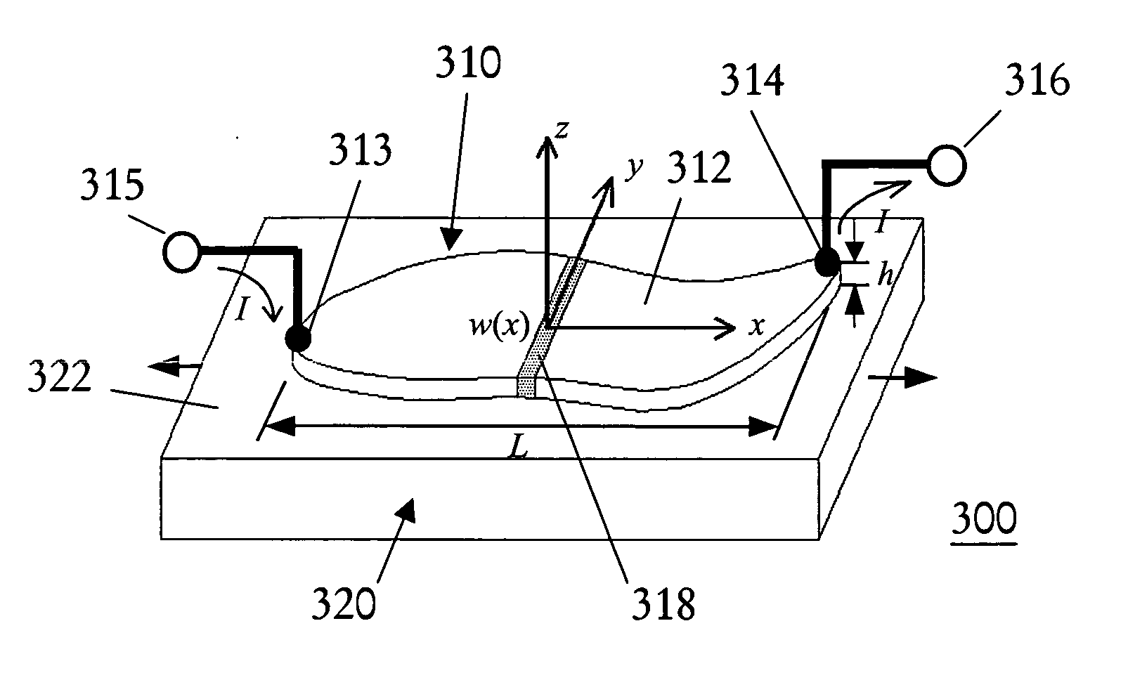
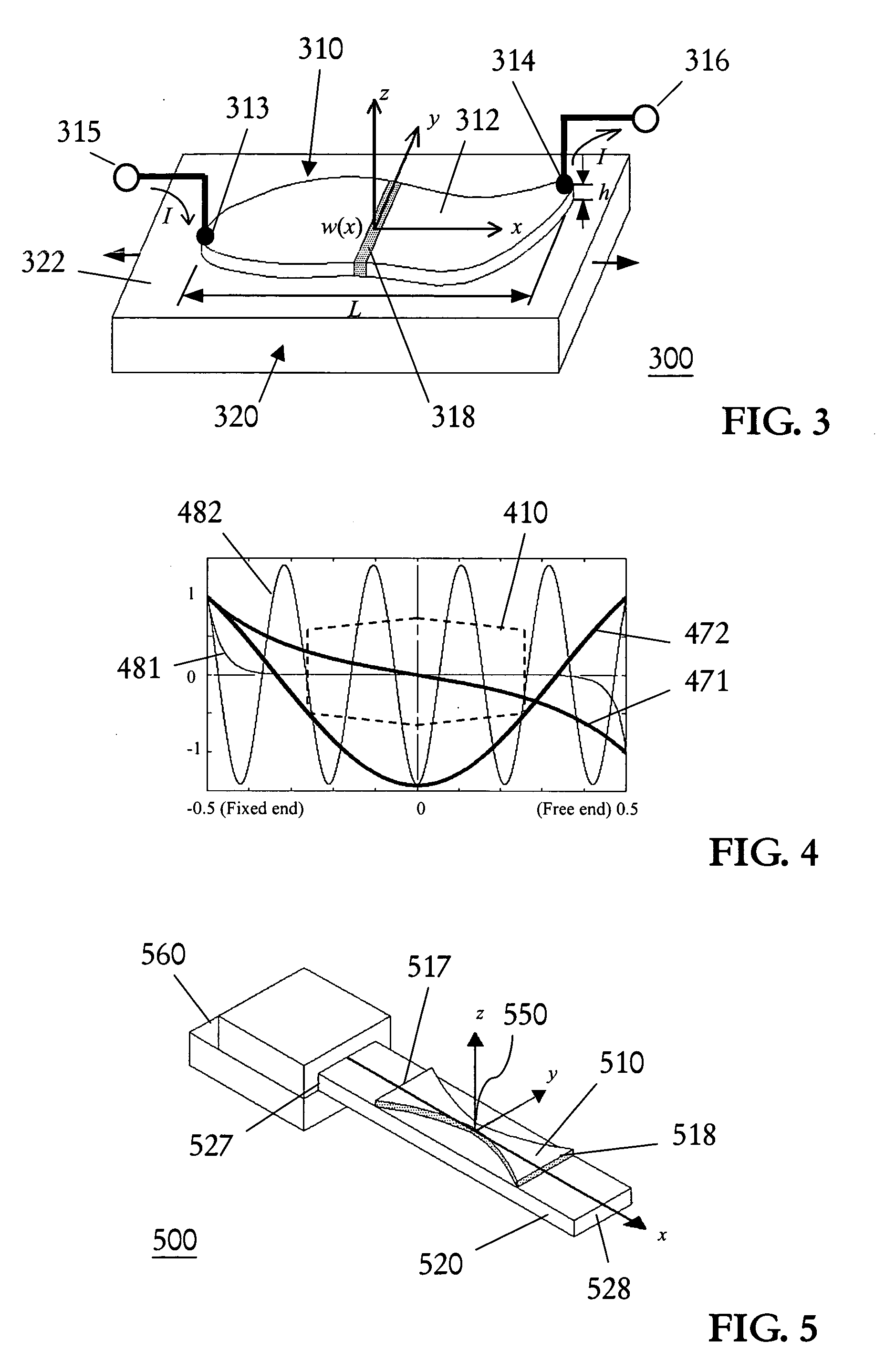
[0049] Any mathematical function can be expressed as a superposition of an even function and an odd function. The strain distribution of any deformation arising in an examined structure, when described with a mathematical function in a model such as illustrated in FIG. 3 and described above, can be one such function. Thus, the strain distribution ε(x) of a structure deformed under mechanical stress becomes

ε(x)=εε(x)+εo(x)  (11)

where εe(x) and εo(x), respectively, are the even and odd components of the mathematical system.

[0050] In accordance with the underlying mathematical conception of the present invention, the surface integral obtained by performing surface integration in the spatial domain can be resolved into a specific solution that facilitates a no-phase-delay low-pass filter into the transfer function of the sensor output. The idea can be outlined in the following expression

R(x)ε(x)dx=R(x)[εe(x)+ε0(x)]dx,  (12)

wherein R(x) is the effective surface electrode acting as...


PUM


Abstract

A strain gauge apparatus having a point-distributed sensor for measuring the strain of a mechanical structure. The strain gauge comprises a thin elongated piezoresistive lamina with a shape contour that is symmetric with respect to the longitudinal axis thereof, and the width of the lamina at the center along the longitudinal axis is minimum for the entire lamina length. The point-distributed strain gauge apparatus measures both static and dynamic deformation in the measured structure at a precise location aligned to the targeted center of the sensor lamina.

Description

BACKGROUND OF THE INVENTION [0001] 1. Field of the Invention [0002] This invention relates in general to a strain gauge for measuring strain information in a structure under mechanical load In particularly, this invention relates to a resistance strain gauge apparatus having a point-distributed sensor for the measurement of true strain at an exact point on a structure sustaining static or dynamic deformation. [0003] 2. Technical Background [0004] Strain gauge is a device for measuring the strain information on the surface of a solid that occur when the body is deformed. A strain gauge is comprised of a sensor laminate; it can be adhered onto the surface or embedded inside the body of a testing structure for measuring strain information of interest. With proper arrangement, complete strain distribution information of a test structure can be measured, such as utilizing a Rosette strain gauge. They are used either to obtain information from which stresses in bodies can be calculated. O...

Claims


Application Information

Patent Timeline
IPC IPC(8): G01L1/00G01L1/22
CPCG01L1/2287
Inventor HSU, YU-HSIANGLEE, CHIH-KUNG
Owner LEE CHIH KUNG
Learn More