
Muffler system for a compressor

a compressor and muffler technology, applied in the field of muffler systems, can solve the problems of affecting the operation efficiency of the compressor, affecting the noise source, and causing noise, so as to reduce the overall size of the compressor housing, reduce the pressure pulsation, and not adversely affect the compressor operation efficiency

Inactive Publication Date: 2005-12-15
BRISTOL COMPRESSORS INT
View PDF48 Cites 9 Cited by
  • Summary
  • Abstract
  • Description
  • Claims
  • Application Information

AI Technical Summary

Benefits of technology

The present invention relates to a muffler system for a compressor that reduces pulsation and sound radiation. The system includes a side-branch muffler and an expansion muffler that work together to minimize pulsation at a specific frequency. The system also includes an exhaust system that connects the mufflers and reduces pressure pulsation at a different frequency. The invention allows for a smaller compressor housing size and improved operating efficiency.

Problems solved by technology

While different compressor designs may result in different noise generation mechanisms and overall different noise profiles, there are common sources of noise for the various types of compressors.
One common source of noise originates in the exhaust gas at the discharge where the noise takes the form of a pressure pulsation.
The pressure pulsation can transmit noise through the compressor housing at the point of discharge tube penetration, or can propagate further downstream and induce noise upon contacting other components of the refrigeration system.
As can be seen, this sound is particularly undesirable when the system is located within, adjacent to or near a living area or a work area.
While a muffler having an expansion chamber located adjacent to the discharge head can prevent pressure pulsation from propagating downstream, it has been found that placement of an expansion chamber muffler adjacent the discharge head reduces operating efficiency of the compressor, while also increasing the overall size of the compressor.

Method used


Image

  • Muffler system for a compressor
  • Muffler system for a compressor
  • Muffler system for a compressor

Examples


Embodiment Construction

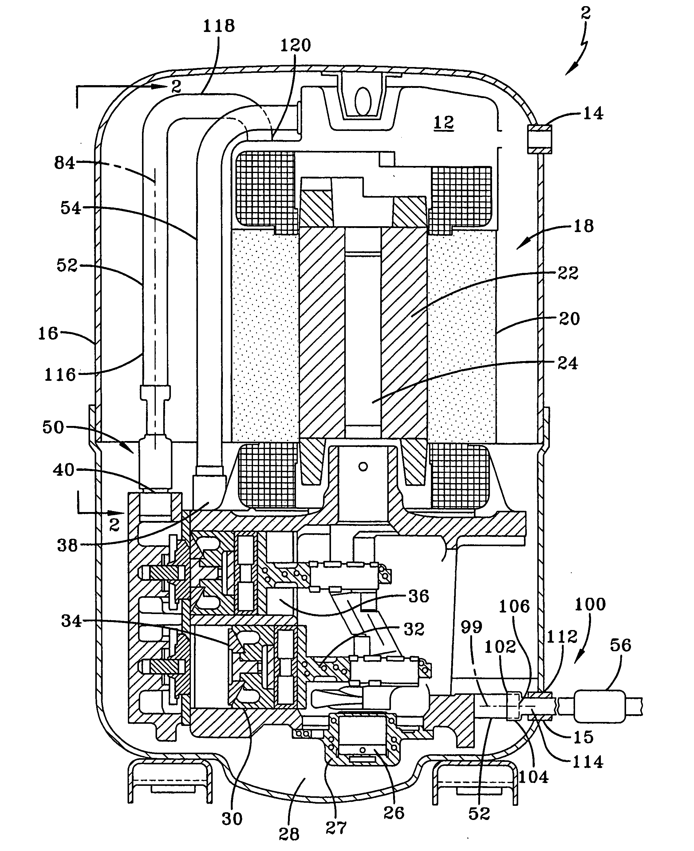
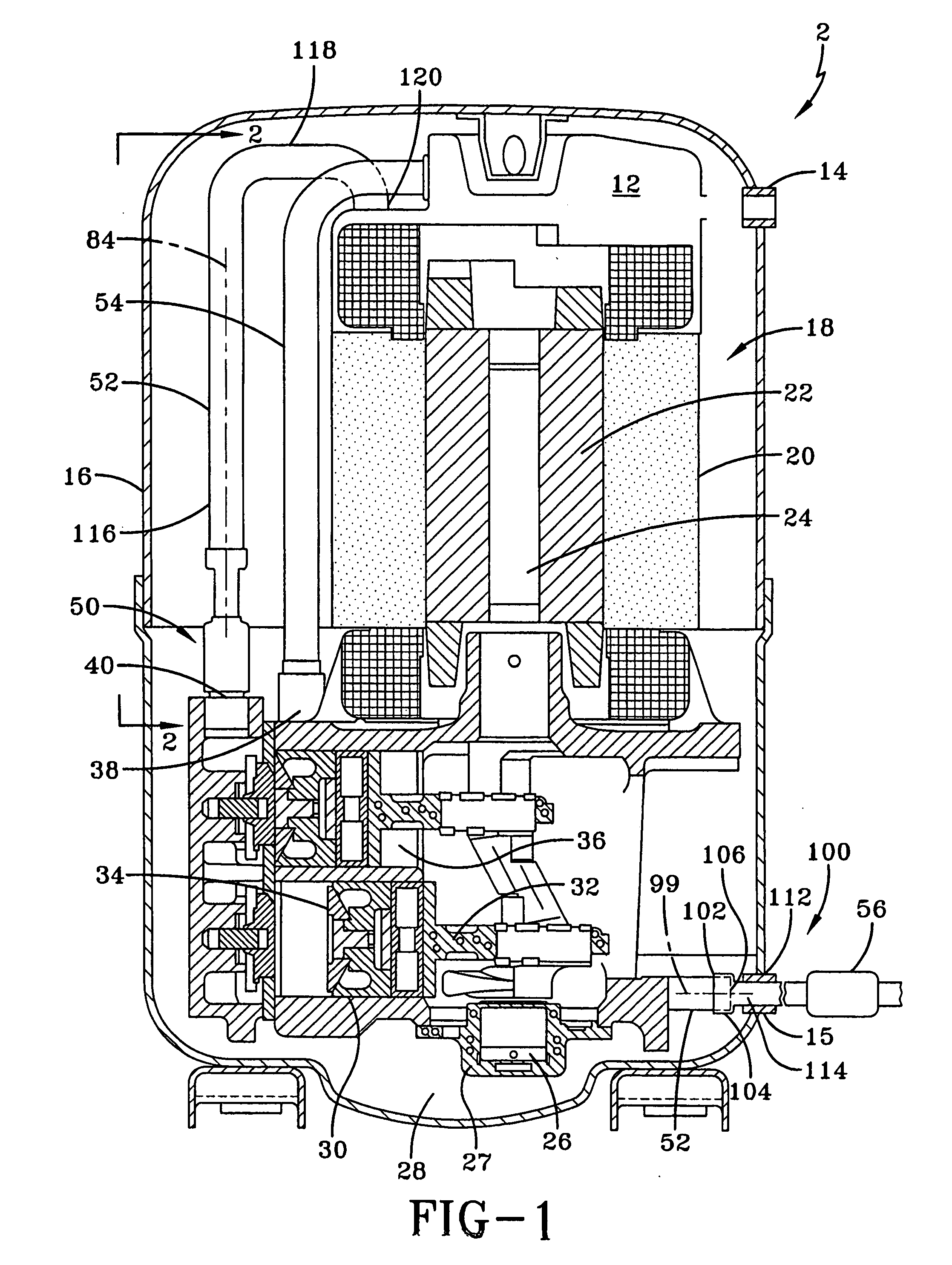
[0020] One embodiment of a compressor that incorporates the muffler system of the present invention is depicted in FIG. 1. Compressor 2 is connected to a conventional refrigeration or heating, ventilation and air conditioning and refrigeration (HVAC&R) system (not shown), such as may be found in a refrigerator, home or automobile. The HVAC&R system has a condenser, expansion device and evaporator in fluid communication. Compressor 2 is preferably a reciprocating compressor connected to an evaporator (not shown) by a suction line that enters the suction port 14 of compressor 2, although the muffler system may be used with any compressor, including, for example, a rotary, screw, or scroll compressor. Suction port 14 is in fluid communication with suction plenum 12. Refrigerant gas from the evaporator enters the low-pressure side of compressor 2 through suction port 14 and then flows to the suction plenum 12 before being compressed.

[0021] Compressor 2 includes an electrical motor 18. ...


PUM


Abstract

A muffler system for a compressor includes an expansion chamber muffler for reducing pressure pulses at the compressor's fundamental pulsation frequency and a side-branch muffler for filtering high-frequency pressure pulses. The expansion muffler is positioned along the compressor discharge stream at a location that maximizes pulsation reduction at the compressor's fundamental pulsation frequency. The side-branch muffler is tuned to the frequency at which the pulsation reduction for the expansion muffler is at a minimum.

Description

CROSS REFERENCE TO RELATED APPLICATIONS [0001] This Application is a continuation in part of application Ser. No. 10 / 441,306, filed May 19, 2003.FIELD OF THE INVENTION [0002] The present invention is directed to a muffler system for use with a compressor, and more specifically to a muffler system having an internal muffler and an external muffler for use with the high-pressure discharge side of a compressor used in refrigeration, cooling and heating systems. BACKGROUND OF THE INVENTION [0003] Compressors are one of several components in cooling and heating systems. They are an important component as the compressor is used to compress refrigerant gas used in the system, raising the pressure and the temperature of the gas. The compressor is typically used in combination with a condenser, expansion valves, an evaporator and blowers to heat or cool a space. Depending on the direction of the refrigerant flow upon exiting the compressor, the system can be used to remove heat from a presel...

Claims


Application Information

Patent Timeline
Patent Type & Authority Applications(United States)
IPC IPC(8): F04B39/00F04B39/12F04B49/03F04B49/10
CPCF04B39/0061F04B39/123Y10S181/403F04B49/10Y10S417/902F04B49/03
Inventor MARSHALL, STEVEN EDWINGILLIAM, DAVID REXMONK, DAVID TURNERMAJERUS, BENJAMIN ALAN
Owner BRISTOL COMPRESSORS INT
Learn More