Data transmission method and receiver

a data transmission and receiver technology, applied in the direction of pulse technique, amplitude demodulation, line-faulst/interference reduction, etc., can solve the problems of multiple access interference (mai) present in the receiver, interference-limited cdma system performance and system capacity points of view, and inability to achieve optimal performance of this kind of receiver

Active Publication Date: 2005-12-15
VIVO MOBILE COMM CO LTD
View PDF12 Cites 10 Cited by
  • Summary
  • Abstract
  • Description
  • Claims
  • Application Information

AI Technical Summary

Benefits of technology

[0011] The invention provides several advantages. In an embodiment of the invention symbol information is stored over a predetermined period (over a transmission time interval, for instance) which enables gathering signal energy of also in repetition coding repeated symbols. The quality of tentative decisions is improved because a greater amount of the energy of the transmitted signal can be collected and used in the decision-making. Additionally, remarkable savings in time-delay can be achieved.

Problems solved by technology

As partly discussed in the authoritative book Holma, Toskala: WCDMA for UMTS, Radio Access for Third Generation Mobile Communications, John Wiley & Sons, Ltd, 2000, CDMA systems are interference-limited from both the receiver performance and system capacity points of view.
The interference-limited nature of CDMA systems results from the receiver design: reception is typically based on a spreading code matched filter (MF) or a correlator.
Since the received spreading codes are usually not completely orthogonal, multiple access interference (MAI) is present in the receiver.
The problem is that the performance of this kind of receivers is not optimal if repetition coding is used in a transmitter because the error rate of de-spread bits increases due to a lower effective coding rate (ECR).
The problem is that the decoding process is time-consuming and therefore causes delay.
Again, the problem is time delay: re-transmission is also a time-consuming process.

Method used


Image

  • Data transmission method and receiver
  • Data transmission method and receiver
  • Data transmission method and receiver

Examples


Embodiment Construction

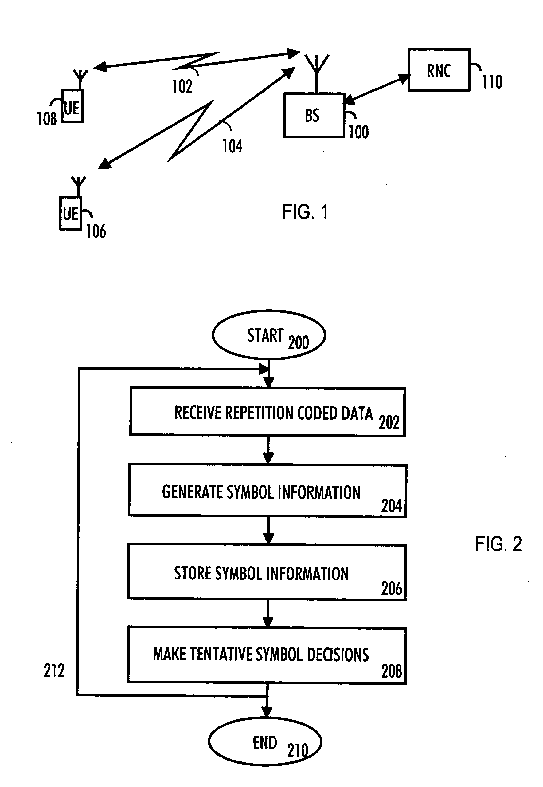
[0017] With reference to FIG. 1, we examine an example of a communication system to which embodiments of the invention can be applied. The present invention can be applied to various wireless communication systems. One example of such a communication system is the UMTS (Universal Mobile Telecommunications System) radio access network. It is a radio access network which includes WCDMA (wideband code division multiple access) technology and can also offer real-time circuit and packet switched services. The embodiments are not, however, restricted to the systems given as examples, but a person skilled in the art may apply the solution to other radio systems provided with the necessary properties.

[0018] It is clear to a person skilled in the art that the method according to the invention can be applied to systems utilizing different modulation methods or air interface standards.

[0019]FIG. 1 is a simplified illustration of a digital data transmission system to which the solution accord...


PUM


Abstract

A receiver of a communication system includes means for receiving repetition-coded data. The receiver also includes means for generating symbol information from the received repetition-coded data. The receiver also includes means for storing symbol information over a predetermined period and means for making tentative symbol decisions by combining the stored symbol information.

Description

FIELD [0001] The invention relates to a data transmission method and a receiver. BACKGROUND [0002] As partly discussed in the authoritative book Holma, Toskala: WCDMA for UMTS, Radio Access for Third Generation Mobile Communications, John Wiley & Sons, Ltd, 2000, CDMA systems are interference-limited from both the receiver performance and system capacity points of view. The interference-limited nature of CDMA systems results from the receiver design: reception is typically based on a spreading code matched filter (MF) or a correlator. Since the received spreading codes are usually not completely orthogonal, multiple access interference (MAI) is present in the receiver. [0003] Sub-optimal multi-user receivers have been developed for fighting multiple access interference. Multi-user receivers can be categorised in several ways: one is to classify the receivers to two main classes: linear equaliser and subtractive interference cancellation (IC) receivers. Linear equalisers, for example...

Claims


Application Information

Patent Timeline
IPC IPC(8): H04BH04B1/10H04B1/707H04L1/00
CPCH04B1/7105
Inventor HORNEMAN, KARIPAJUKOSKI, KARITIIROLA, ESA
Owner VIVO MOBILE COMM CO LTD
Why Eureka
Try Eureka