Polyphase diode driver

a diode driver and polyphase technology, applied in the field of diodes, can solve the problems of large devices with relatively high local dissipation of ortiz, and achieve the effects of low cost construction, superior performance and high efficiency

Active Publication Date: 2005-12-15
ANALOG MODULES
View PDF8 Cites 24 Cited by
  • Summary
  • Abstract
  • Description
  • Claims
  • Application Information

AI Technical Summary

Benefits of technology

[0006] It is therefore a general object of the invention to supply a continuous or pulsed constant current to a light emitting diode or diodes (LED) load with miniature size, low-cost construction, high efficiency, and superior performance, using a circuit capable of implementation with modern miniature surface mount components. As used herein, an “LED” load includes a laser diode or array of laser diodes. As used herein, “constant current” means essentially constant current, regardless of the actual voltage across the LED load, which can vary.

Problems solved by technology

In comparison, Ortiz uses individual large devices with relatively high local dissipation.

Method used


Image

  • Polyphase diode driver
  • Polyphase diode driver
  • Polyphase diode driver

Examples


Embodiment Construction

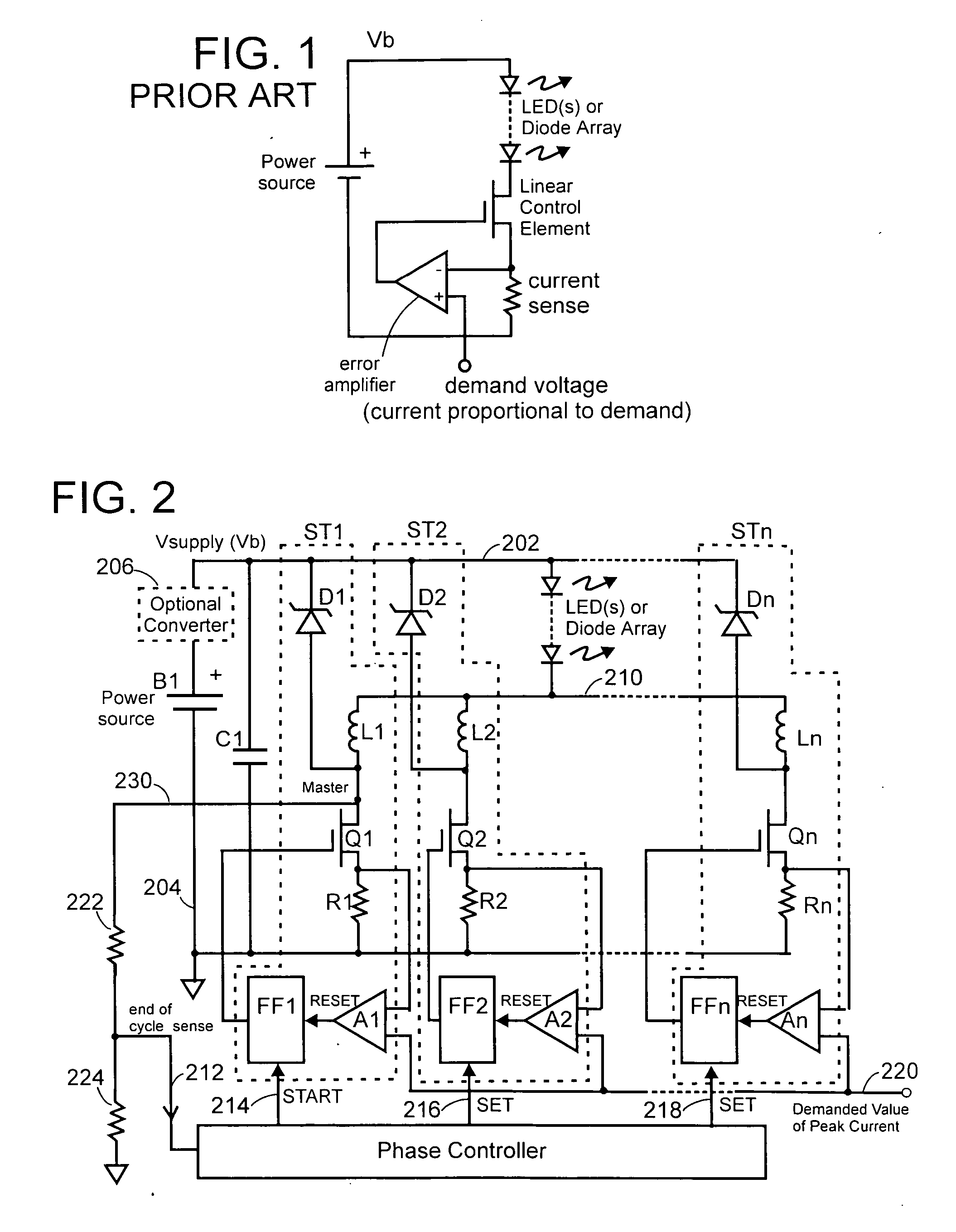
[0024]FIG. 2 illustrates schematically an embodiment of the polyphase diode driver of the present invention having a number “n” of stages for driving a load that may be an LED, a plurality of LEDs, or a diode array, such as laser diodes. When the load is referred to hereinafter as an “LED”, it should be understood that any of these loads are being referred to. There are at least two driver stages.

[0025] In this example of the polyphase diode driver, three driver stages—ST1, ST2 and STn—are illustrated, and are described in greater detail hereinbelow.

[0026] A power source B1 is connected between a supply line 202 (Vsupply) and a return line (ground) 204. A storage capacitor C1 is connected between the supply line 202 and ground 204. An LED load has one end connected to the supply line 202 and another end connected to a common LED drive terminal (common cathode in FIG. 2) 210 that is the common outputs of the plurality of driver stages ST1, ST2 and STn. (The outputs of the driver st...


PUM


Abstract

A driver supplying a total current to a load has a plurality (n) of driver stages (ST1 . . . STn). One stage is a master stage. Each driver stage has a switching device (Q) and an inductor (L) connected in series between the switching device and the output of the driver stage. The switching devices are turned ON in sequence with one another, during a cycle time (Tc) which is determined by sensing current through the inductor (L1) in the master stage. When the switching device is turned ON current through the inductor rises, when the inductor current reaches the value of a demanded current the switch is turned OFF, and after the switch is turned OFF the inductor continues to supply (output) current to the load with a current which ramps down. A rectifying device (D) connected between the inductor and the supply line allows current to continue to flow in the inductor and be supplied to the load after the switch is turned OFF.

Description

CROSS-REFERENCE TO RELATED APPLICATIONS [0001] This is a non-provisional, continuation-in-part of U.S. Provisional Patent Application No. 60 / xxx,xxx filed Jun. 9, 2004 by Crawford et al.TECHNICAL FIELD OF THE INVENTION [0002] This invention relates to diode drivers that provide a constant, controlled, pulsed, or variable current into a light emitting diode (LED) or array of light-emitting diodes, including laser diodes. BACKGROUND OF THE INVENTION [0003] Analog constant current sources or pulsed analog constant current sources using linear dissipative pass elements have been used as diode drivers to power light emitting diodes, often laser diodes. FIG. 1 illustrates an array of LEDs (or diode array) that are connected to a power source. A linear control (pass) element is disposed in the return path from the LED array to the power source. Current flowing through the LEDs flows through a current sense resistor which supplies a voltage indicative of current to an input of an error ampl...

Claims


Application Information

Patent Timeline
Patent Type & Authority Applications(United States)
IPC IPC(8): H01S3/00H01S5/042
CPCH05B33/0815H01S5/042H05B45/3725
Inventor CRAWFORD, IAN D.HARWICK, JOHNMORALES, MIGUEL
Owner ANALOG MODULES
Why Eureka
Try Eureka