Eureka AIR delivers breakthrough ideas for toughest innovation challenges, trusted by R&D personnel around the world.

Platform level overload control

a platform-level and overload control technology, applied in the field of wireless communication systems, can solve problems such as the inability to solve overload problems, the data flow in a wireless network is typically burst, and the processor capacity is exceeded, and the simple drop of the lowest priority message may not solve the overload problem

Inactive Publication Date: 2005-12-15
LUCENT TECH INC
View PDF6 Cites 96 Cited by
  • Summary
  • Abstract
  • Description
  • Claims
  • Application Information

AI Technical Summary

Benefits of technology

"This patent describes a way to control message overload in a communication system with multiple networks. It uses translated priority information to select which messages to throttle, based on their importance and the rate at which they are coming in. This approach allows for a generic overload control algorithm to be used across different networks, making it easier to manage message overload. The method can involve dropping or delaying certain messages, and can be implemented at both the platform and network levels. Overall, this invention provides a more efficient and effective way to handle message overload in complex communication systems."

Problems solved by technology

There are times, however, when the PO exceeds the controller capacity and measures must be taken to handle such overload situations.
Data flow in a wireless network is typically bursty; there may be periods with low volumes and others with high volumes.
It follows that even with a manageable average traffic volume, a processor may experience instantaneous processing loads that exceed the average value and may exceed the processor capacity.
Simply dropping the lowest priority messages may not solve an overload problem where a large number of high priority messages are arriving within a certain time interval.
Opening each message is computationally expensive.
An overload control algorithm that imposes too high of a computational cost to determine priority information typically is not used because of the additional computational cost.
Another layer of complexity is presented by the fact that each different network (i.e., UMTS, EV-DO, CDMA, TDMA, etc.) has its own signaling and traffic messages.
Developing separate control algorithms for each network or technology adds complexity to the systems and increases cost because of the duplication of efforts in overload control development and implementation.

Method used


Image

  • Platform level overload control
  • Platform level overload control

Examples


Embodiment Construction

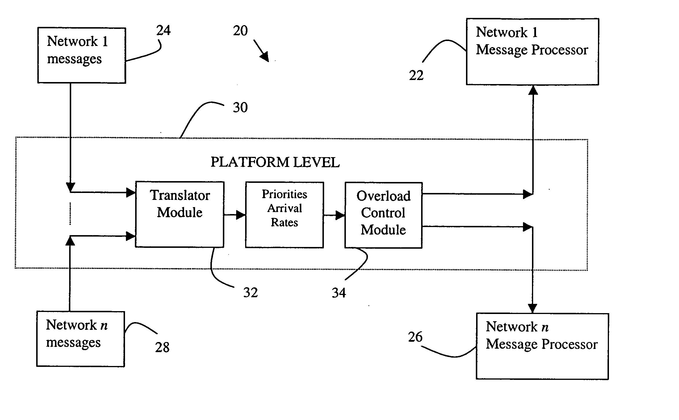
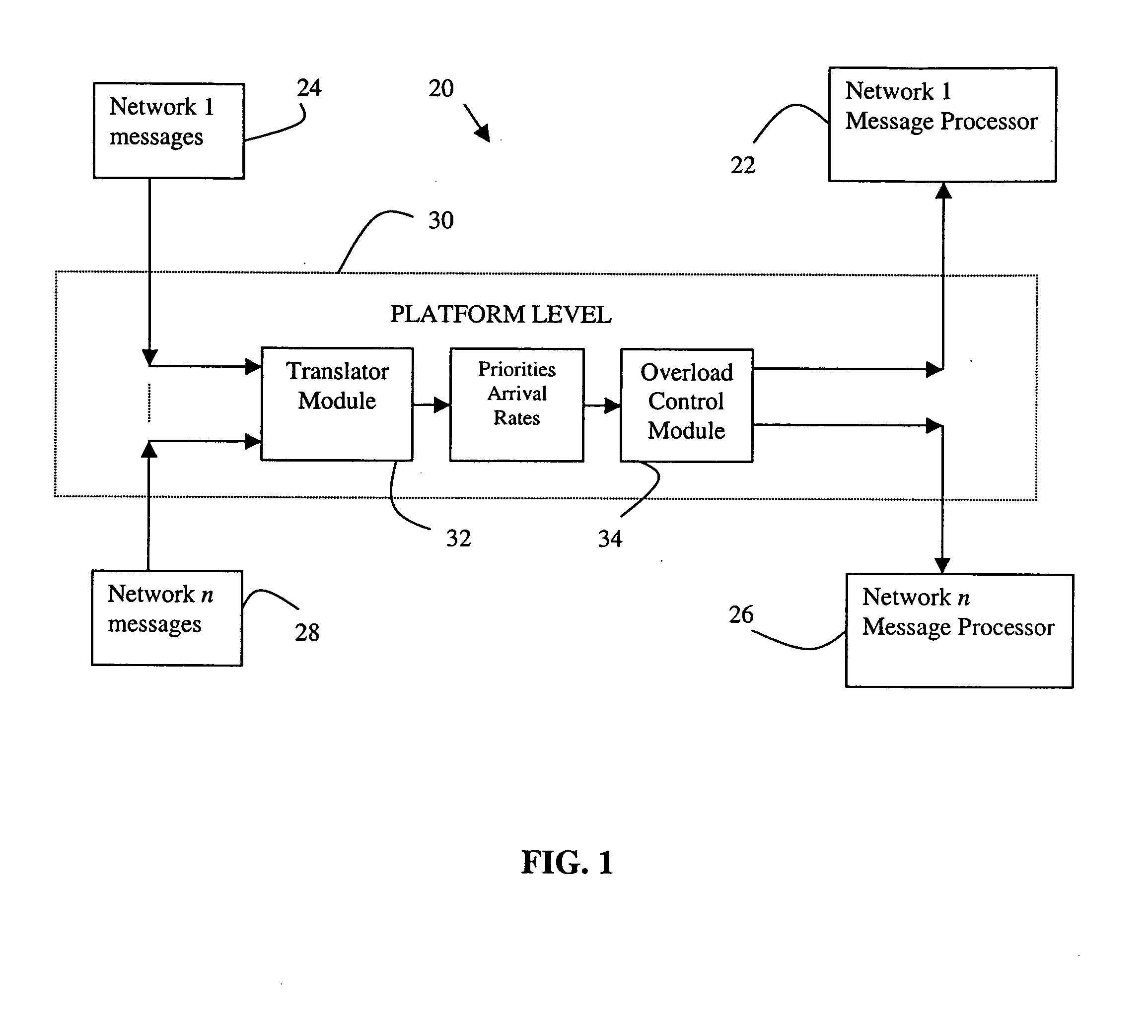
[0018]FIG. 1 schematically shows portions of a communication system 20 that is useful for facilitating wireless communications among mobile customers, for example. The example system includes a plurality of networks at a network level. A first example network includes a message processor 22 that processes a plurality of messages 24 in a known manner. Another network message processor 26 is associated with another network for processing plurality of messages 28 in a known manner. Although two network message processors are shown, the example system 20 may include more networks or just one. In one example system, the different networks utilize different technologies such as UMTS, EV-DO, CDMA, TDMA, for example.

[0019] Each network processor has a maximum processor occupancy (PO) based on the memory and processing speed of the particular network elements selected. In most situations, the processors are capable of handling message traffic. There are times, however, when the volume of me...


PUM


Abstract

A communication system includes overload control at a platform level. A translator module receives messages from any number of distinct networks and provides priority information regarding each of those messages to an overload control module that uses the translated priority information and arrival rate information to provide needed message traffic control. The disclosed arrangement provides a universally applicable overload control approach that reduces duplicated resources associated with individual overload control algorithms for each network message processor.

Description

FIELD OF THE INVENTION [0001] This invention generally relates to telecommunications, and more particularly to wireless communication systems. DESCRIPTION OF THE RELATED ART [0002] Wireless communication systems have grown increasingly in popularity and in capabilities. Current systems provide voice communication, data communication and other multi-media applications. As technology progresses, the capabilities in these areas continue to improve. [0003] Managing the flow of information in such systems is of critical importance. For example, a variety of messages must be processed by a system controller for optimal communications to be maintained. Typical controllers or processors have a maximum capacity. Under most circumstances, the capacity is not reached and the processor occupancy (PO) is at a level that allows for effective maintenance of the desired communications among subscribers within a network, for example. There are times, however, when the PO exceeds the controller capac...

Claims


Application Information

Patent Timeline
Patent Type & Authority Applications(United States)
IPC IPC(8): G01R31/08H04L12/56
CPCH04L47/10H04L47/12H04L47/2433H04W92/02H04W4/18H04W28/08H04L47/32
Inventor KUMAR, GOPAL N.FISHKIN, STACY GAIL
Owner LUCENT TECH INC
Why Eureka
Eureka Blog
Learn More