
Insertion of embedded test in RTL to GDSII flow

Inactive Publication Date: 2005-12-08
LOGICVISION
View PDF16 Cites 23 Cited by
  • Summary
  • Abstract
  • Description
  • Claims
  • Application Information

AI Technical Summary

Benefits of technology

[0011] The present invention seeks to provide a method and program product for quickly analyzing RTL circuit descriptions, incorporating into the RTL circuit description of test logic of objects necessary to implement a scan test and provide an RTL description of the test logic that is insensitive to the final implementation of the cir

Problems solved by technology

However, there are two major drawbacks to modification of the RTL description to describe scan chains.
First, the scan chains descriptions have a dramatic impact on the RTL description because it affects most of the original RTL description.
This makes it very difficult for the IC designer to debug.

Method used


Image

  • Insertion of embedded test in RTL to GDSII flow
  • Insertion of embedded test in RTL to GDSII flow
  • Insertion of embedded test in RTL to GDSII flow

Examples


Embodiment Construction

[0019] In the following detailed description, numerous specific details are set forth in order to provide a thorough understanding of the present invention, However, it will be understood by those skilled in the art that the present invention may be practiced without these specific details. In other instances, well known methods, procedures, components and circuits have not been described in detail so as not to obscure aspects of the present invention.

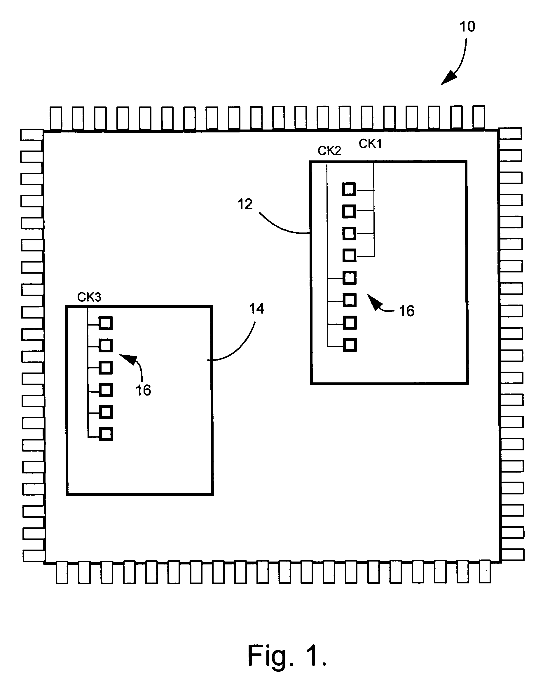
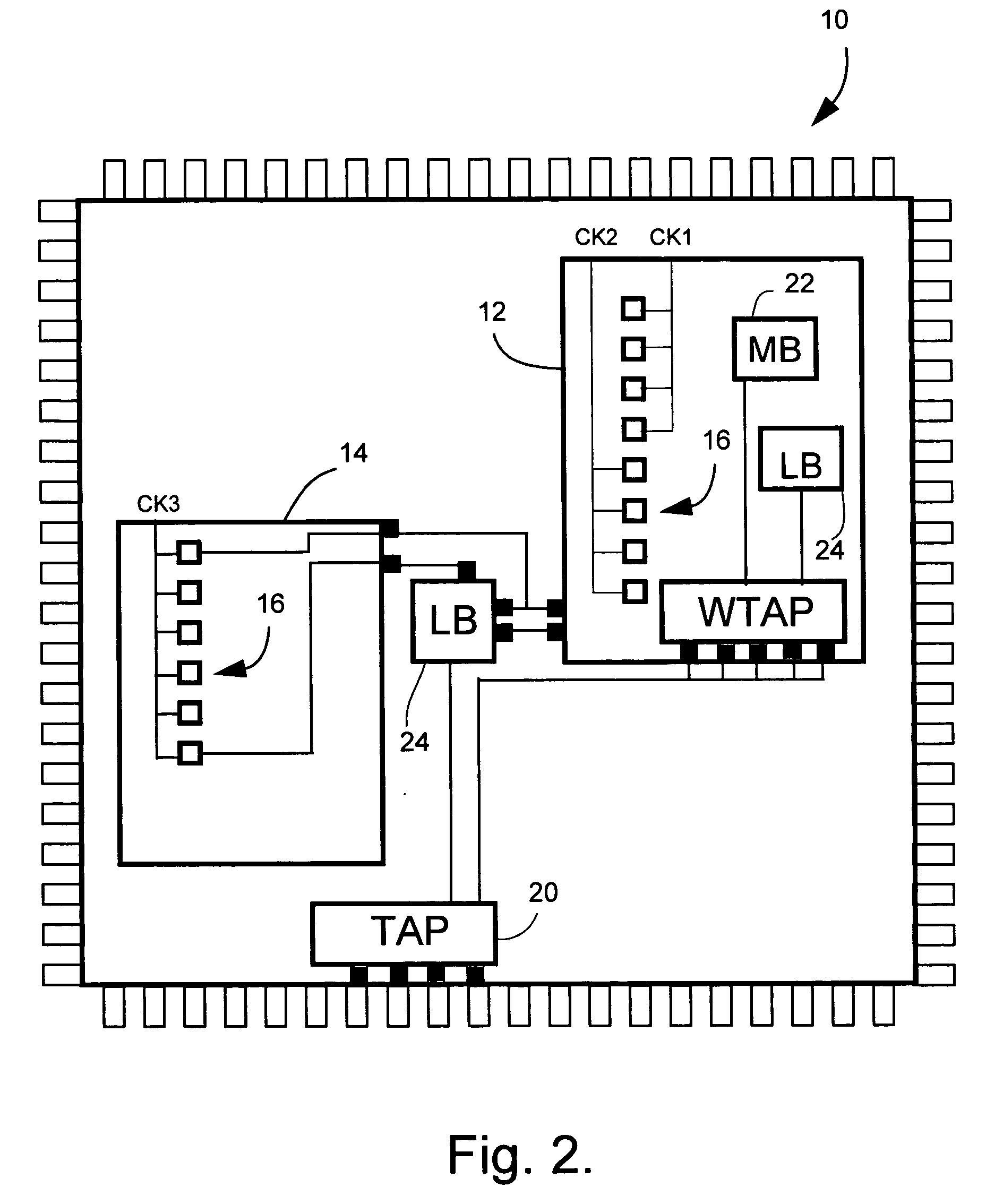
[0020]FIG. 1 diagrammatically illustrates a simple circuit 10 as developed by a circuit design engineer. The circuit has two cores 12 and 14, each having a plurality of functional memory elements 16 associated with respective clock domains. It is desired to insert test objects into the circuit RTL. Examples of test objects are an IEEE test access port (TAP), logic test controllers, memory test controllers, PLL BIST and the like. As compared to insertion of scan chains, the insertion of such test objects into the circuit RTL has little...


PUM


Abstract

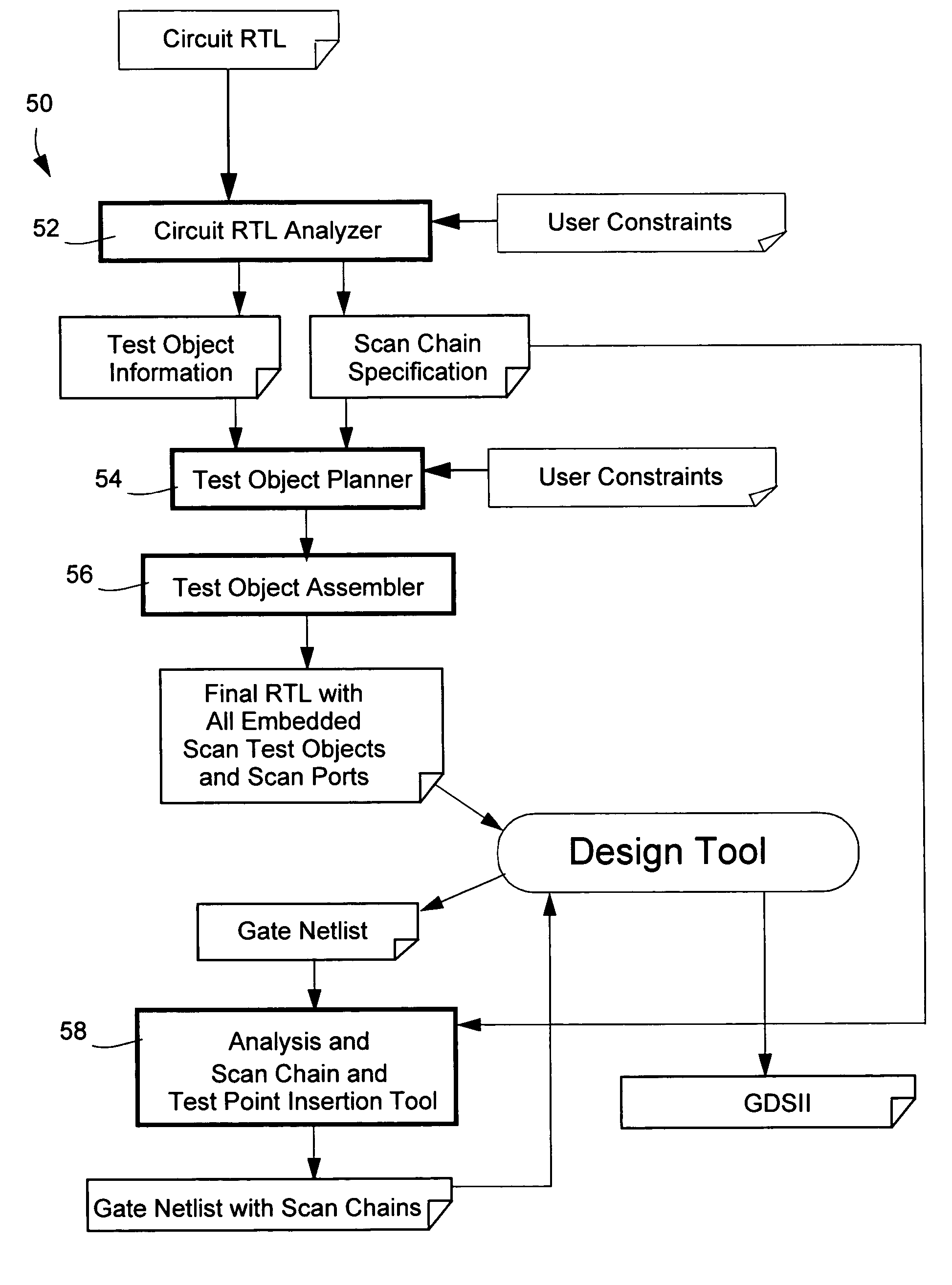
A method of designing a scan testable integrated circuit with embedded test objects for use in scan testing the circuit, comprises compiling a register-transfer level (RTL) circuit description of the circuit into an unmapped circuit description; extracting information from the unmapped circuit description for use in generating and inserting RTL descriptions of test objects into the RTL circuit description and for use in generating and inserting scan chains into the circuit; generating and inserting the RTL descriptions of the test objects into the RTL circuit description to produce a modified RTL circuit description; storing the modified RTL circuit description; synthesizing the modified RTL description into a gate level circuit description of the circuit; and constructing and inserting scan chains into the gate level circuit description according to information extracted from the unmapped circuit description.

Description

CROSS-REFERENCE TO RELATED APPLICATIONS [0001] This application claims the benefit of U.S. Provisional Patent Application Ser. No. 60 / 577,171 filed Jun. 7, 2004, incorporated herein by reference.BACKGROUND OF THE INVENTION [0002] 1. Field of the Invention [0003] The present invention generally relates to designing of integrated circuits (“IC” or “chip”) and, more specifically, to a method and program product for implementing scan-test objects into a register-transfer level (RTL) circuit description of integrated circuits and extracting additional information useful in implementing scan chains and, optionally, test points in a gate-level description. [0004] 2. Description of Related Art [0005] In the design of integrated circuits, it is commonplace for circuit designers to develop a RTL description of the circuit. To provide for scan testing of the circuit, test structures and scan chains are typically inserted into the circuit after the RTL circuit description has been synthesized i...

Claims


Application Information

Patent Timeline
IPC IPC(8): G01R31/28G01R31/3185G06F17/50
CPCG01R31/318583
Inventor COTE, JEAN-FRANCOISNADEAU-DOSTIE, BENOITMAAMARI, FADI
Owner LOGICVISION
Learn More