
Programmatic time-gap defect correction apparatus and method

a defect correction and time gap technology, applied in the field of computer systems, can solve problems such as data corruption that can have serious (even life-threatening) consequences, compromising integrity, and incurred data corruption, and achieve the effect of minimal system resources

Inactive Publication Date: 2005-12-08
AFTG TG L L C
View PDF27 Cites 6 Cited by
  • Summary
  • Abstract
  • Description
  • Claims
  • Application Information

AI Technical Summary

Benefits of technology

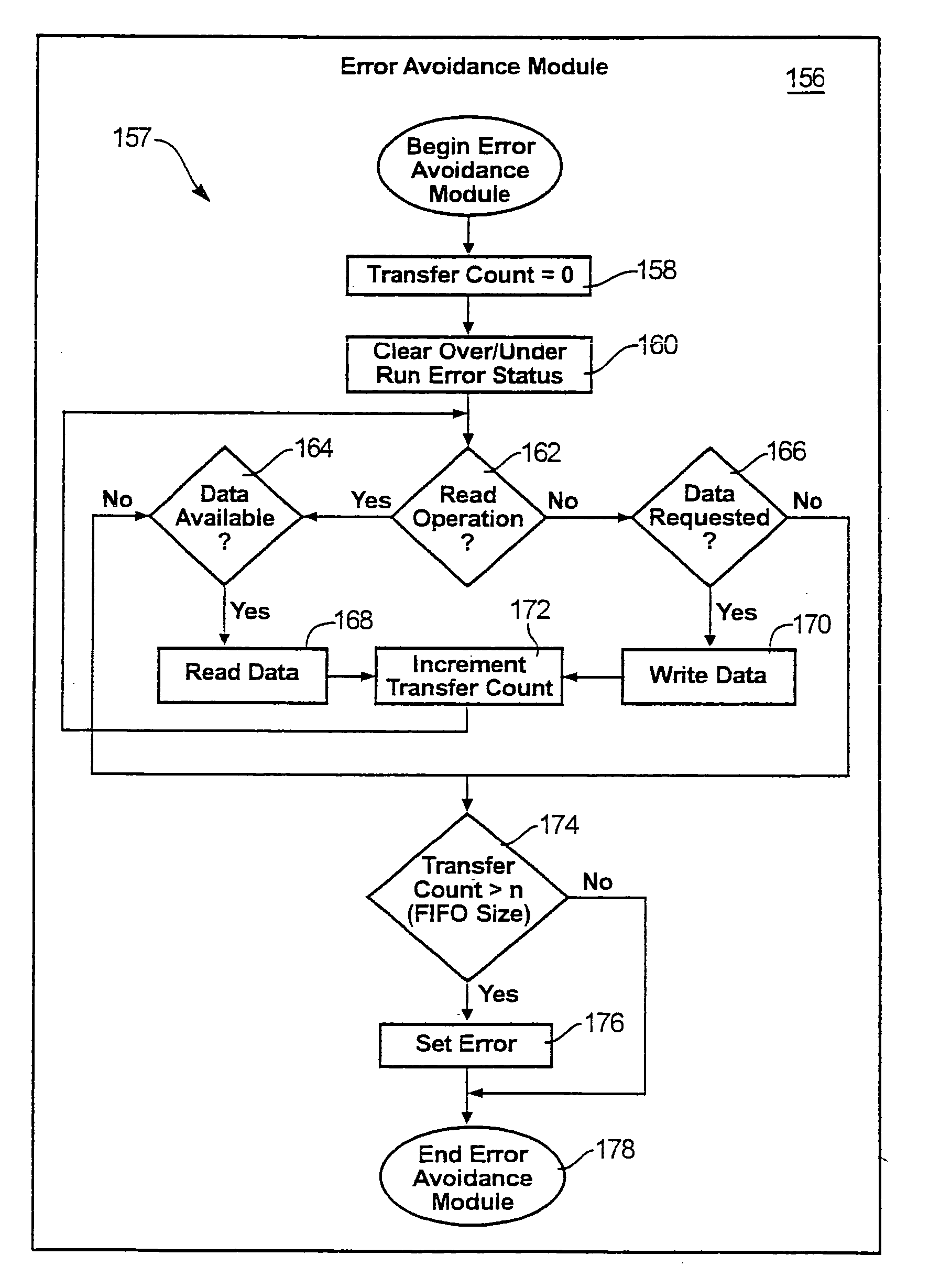
"The patent describes an error avoidance module for a computer system that can prevent errors caused by time-gap defects and data transfers. The module includes a memory device and a processor for processing data structures. It uses a buffer to temporarily store data and a driver to control the exchange of data between devices in the system. The module can detect and prevent errors by counting the number of bytes transferred and comparing it to the buffer capacity. The module can also perform error correction procedures if necessary. Overall, the invention provides a simple and effective way to prevent errors in computer systems."

Problems solved by technology

Maintaining the integrity of the stored data is essential to the proper functioning of these computer systems, and data corruption can have serious (even life-threatening) consequences.
However, computer users expect a computer system not to make inadvertent or incorrect changes to data, compromising its integrity.
When these inadvertent or erroneous changes do occur, data corruption is incurred.
The causes of data corruption may be numerous, including electronic noise, defects in physical hardware, hardware design errors, and software design errors.
Hardware design flaws may result from oversights or inaccuracies in specifying timing, function, or requirements for interfacing with other hardware in a circuit or computer system.
If insufficient design margin is provided or timing errors cause signals to be read at incorrect times, data corruption may result.
Thus, even when data may be stored correctly in memory devices or calculations are performed correctly by a processor, data may be corrupted when transferred between hardware devices due to timing inconsistencies or insufficient design margin.
Software may contain glitches or logical flaws.
In certain hardware systems, time gaps may exist in which erroneous data transfers between devices may occur, yet remain undetected by the hardware involved.
In some cases, occurrences of data corruption may be exacerbated by the arbitration that occurs between devices in a computer system.
That is, because of the increase in handshaking, exchanges, and buffering that occurs between devices in a computer system, conditions may exist wherein errors may be incurred, yet remained undetected to the computer system.
As a result, a computer system may increase in complexity due to increases in arbitration needed to pass information between the buses, ports, devices, bridges, and the like.
Additionally, computer designers may design a computer system to be backward compatible with older and slower devices, but may provide insufficient error correction support for these devices in order not to slow overall system performance.
One problem may be that a CPU actually sends or requests data before a controller can instruct it not to do so.
The result is that data may be lost and in some cases may go undetected to the hardware involved in the data transfer.
These types of problems may increase in frequency and number as newer and faster devices are interfaced to older legacy controllers and devices.
Buffer underruns and overruns may occur when data is not provided to or read from a buffer quickly enough and may incur errors in a data transfer.
As a result, errant values may be incorrectly read from an empty buffer or data may be lost when the buffer is overrun.
However, if time-gap defects exist between I / O controllers and other devices in a computer system, interrupts may not arrive within the necessary time-frame to be properly responded to.

Method used


Image

  • Programmatic time-gap defect correction apparatus and method
  • Programmatic time-gap defect correction apparatus and method
  • Programmatic time-gap defect correction apparatus and method

Examples


Embodiment Construction

[0037] It will be readily understood that the components of the present invention, as generally described and illustrated in the Figures herein, could be arranged and designed in a wide variety of different configurations. Thus, the following more detailed description of the embodiments of systems and methods in accordance with the present invention, as represented in FIGS. 1 through 10, is not intended to limit the scope of the invention, as claimed, but is merely representative of certain presently preferred embodiments in accordance with the invention.

[0038] The presently preferred embodiments will be best understood by reference to the drawings, wherein like parts are designated by like numerals throughout.

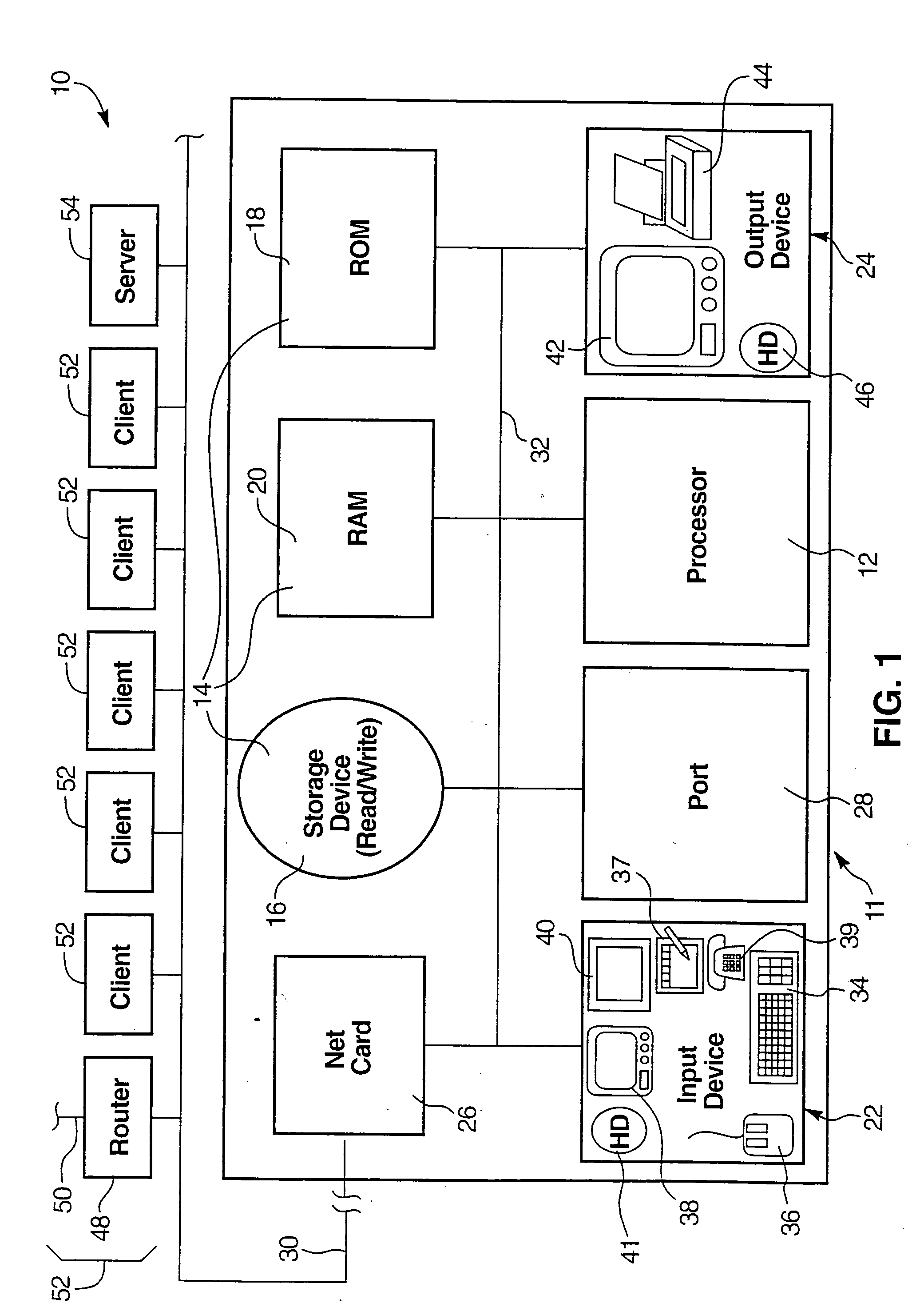
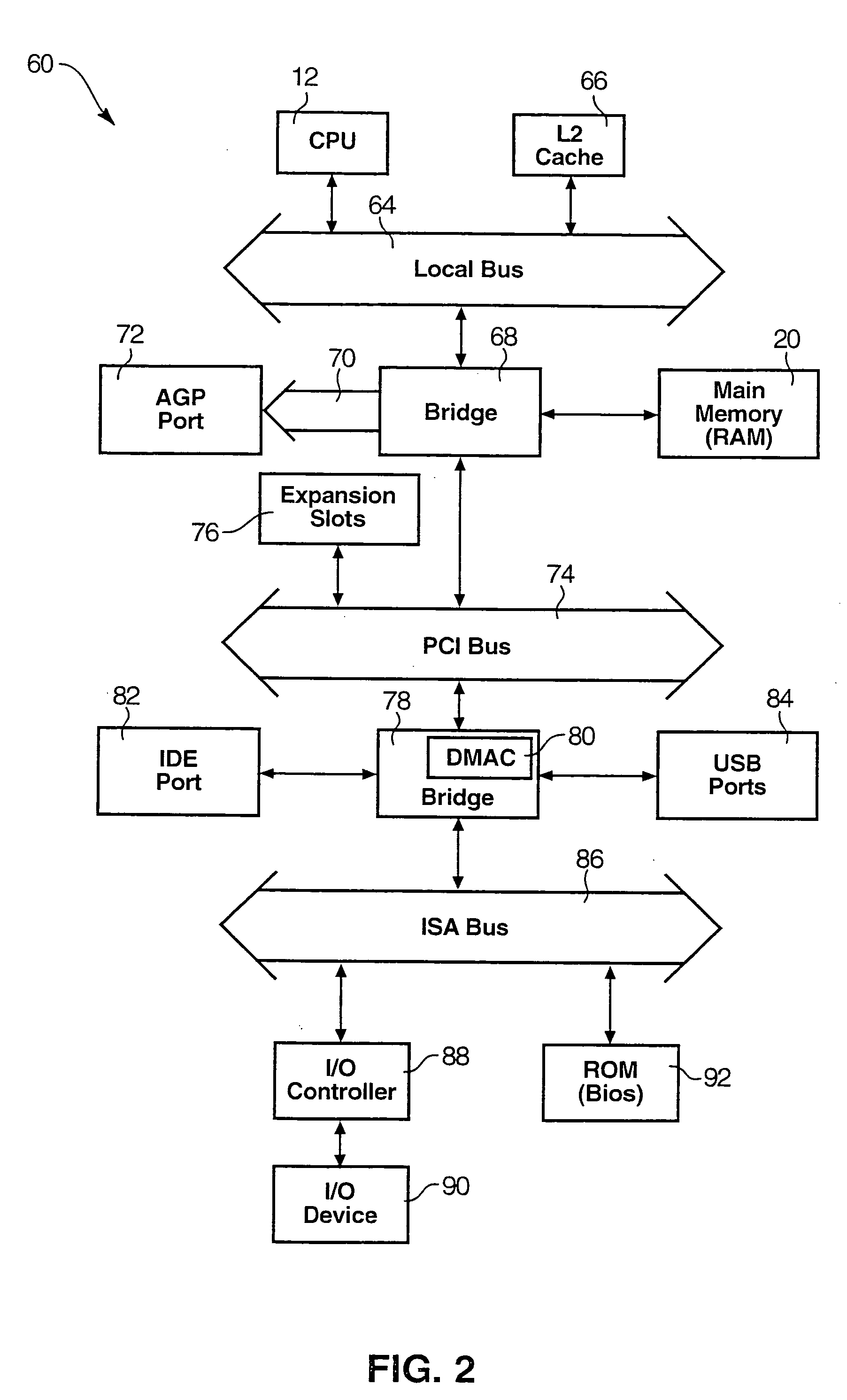
[0039] Referring to FIG. 1, an apparatus 10 may implement the invention on one or more nodes 11, (client 11, computer 11) containing a processor 12 (CPU 12). All components may exist in a single node 11 or may exist in multiple nodes 11, 52 remote from one another. The CPU 1...


PUM


Abstract

A programmatic time-gap defect correction apparatus and method corrects errors which may go undetected by a computer system. Buffer underruns or overruns, which may incur errors in data transfers, yet remain undetected and uncorrected in a computer system, are corrected by an error avoidance module in accordance with the invention. Bytes transferred to and from buffers, used by an I / O controllers to temporarily store data while being transferred between synchronous and asynchronous devices, are counted and an error condition is forced based on the count. If the count exceeds the capacity of the buffer, an error condition is forced, thereby reducing chances that errors are incurred into the data transfer.

Description

RELATED APPLICATIONS [0001] This application is a continuation of co-pending U.S. patent application Ser. No. 10 / 005,135, filed on Nov. 30, 2001 for PROGRAMMATIC TIME-GAP DEFECT CORRECTION APPARATUS AND METHOD.BACKGROUND [0002] 1. The Field of the Invention [0003] This invention relates to computer systems and, more particularly, to novel systems and methods for preventing data corruption due to time-gap defects in computer systems. [0004] 2. The Background Art [0005] Computers are now used to perform functions and maintain data critical to many organizations. Businesses use computers to maintain essential financial and other business data. Computers are also used by government to monitor, regulate, and even activate, national defense systems. Maintaining the integrity of the stored data is essential to the proper functioning of these computer systems, and data corruption can have serious (even life-threatening) consequences. [0006] Computers store information in the form of numeric...

Claims


Application Information

Patent Timeline
Patent Type & Authority Applications(United States)
IPC IPC(8): G06F11/00
CPCG06F11/004G06F11/0745G06F11/076H04L47/10
Inventor ADAMS, PHILLIP M.
Owner AFTG TG L L C
Learn More