Laminated piezoelectric element, liquid droplet ejection head using same, and image forming apparatus comprising same
- Summary
- Abstract
- Description
- Claims
- Application Information
AI Technical Summary
Benefits of technology
Problems solved by technology
Method used
Image
Examples
first embodiment
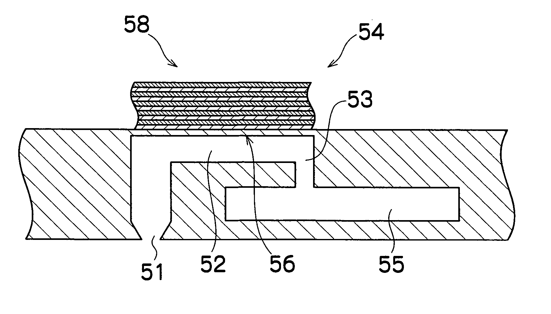
[0104]FIG. 8 is a plan view showing the laminated piezoelectric element according to the present invention. As shown in FIG. 8, the laminated piezoelectric element 58 according to the present embodiment is formed by combining a plurality of band-shaped row electrodes (first electrodes) 90 (row X, . . . , row Xm) and a plurality of band-shaped column electrodes (second electrodes) 92 (column Y1, . . . , column Yn) in a lattice configuration. The thin film-shaped piezoelectric body 94 is sandwiched between the plurality of band-shaped row electrodes (first electrodes) 90 (row X1, . . . , row Xm) and the plurality of band-shaped column electrodes (second electrodes) 92 (column Y1, . . . , column Yn).
[0105] Here, the “lattice configuration” is not necessarily a lattice in which the row electrodes 90 and the column electrodes 92 are orthogonal, and it may also indicate a state where the column electrodes 92 are arranged so as to intersect obliquely with the row electrodes 90 at an angle ...
second embodiment
[0124]FIG. 11 is a plan view that is similar to FIG. 8 shown above. As shown in FIG. 11, in the laminated piezoelectric element 158 of the second embodiment, the row electrodes and the column electrodes are respectively divided into two parts at the central regions of the laminated piezoelectric element 158, by means of a straight line parallel to the row direction and a straight line parallel to the column direction, as indicated by the dotted lines. In this case, by forming the row electrodes 190-1 and 190-2 and the column electrodes 192-1 and 192-2, the laminated piezoelectric element 158 is split into four blocks including an upper left block, an upper right block, a lower left block, and a lower right block. By dividing the electrodes in this fashion and connecting electrode wires through the end portions on either side of the blocks, the electrodes of the respective blocks can be independently driven, and hence it is possible to independently drive the nozzles corresponding to...
third embodiment
[0126] Next, the laminated piezoelectric element will be described.
[0127]FIG. 12 is an oblique perspective view showing the schematic composition of the laminated piezoelectric element according to the third embodiment. FIG. 12 shows the arrangement of the electrodes in particular, and the piezoelectric bodies sandwiched between these electrodes are omitted from the drawings.
[0128] As shown in FIG. 12, the laminated piezoelectric element 258 according to the present embodiment has two or more types of pattern electrodes in the lamination direction, as well as in the row direction and in the column direction. Of the row electrodes 290 arranged in the row direction, row X11, for example, comprises the electrodes that are provided with two parallel electrodes X11a and X11b (row electrodes) and form the electrode pairs activating the active parts together with column electrodes (described hereinafter). Electrodes X11-1, X11-3, and so on, forming the electrode pairs corresponding to th...
PUM
 Abstract
Description
Claims
Application Information
 - R&D
- Intellectual Property
- Life Sciences
- Materials
- Tech Scout
- Unparalleled Data Quality
- Higher Quality Content
- 60% Fewer Hallucinations
Browse by: Latest US Patents, China's latest patents, Technical Efficacy Thesaurus, Application Domain, Technology Topic, Popular Technical Reports.
© 2025 PatSnap. All rights reserved.Legal|Privacy policy|Modern Slavery Act Transparency Statement|Sitemap|About US| Contact US: help@patsnap.com


