
Hinge-Over Riser Assembly

Active Publication Date: 2008-07-31
CHEVROU USA INC
View PDF4 Cites 3 Cited by
  • Summary
  • Abstract
  • Description
  • Claims
  • Application Information

AI Technical Summary

Benefits of technology

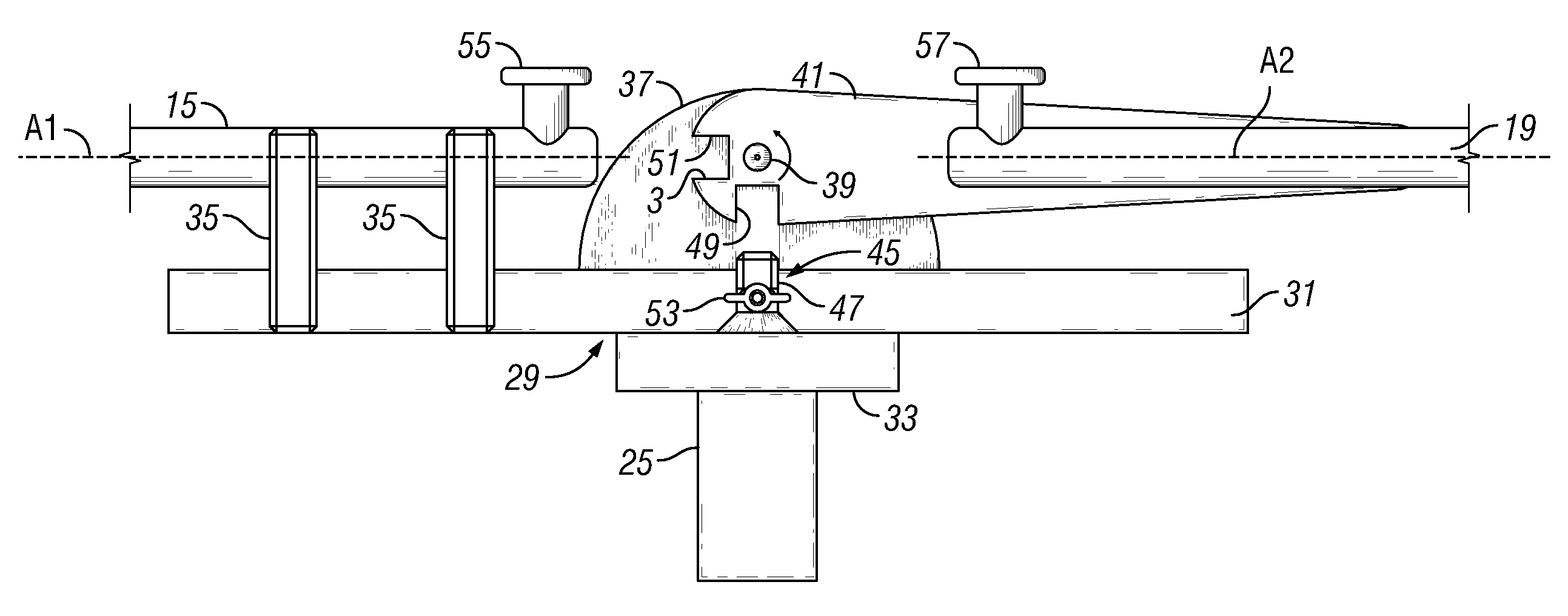
[0016]The method can also include that the subsea jumper is fabricated prior to the step of lowering the first end of the flowline, pursuant to predetermined dimensions such that the subsea jumper can readily connect between the flowline opening and the riser opening after the riser is lifted to rotate the riser about the hinge-over joint.

Problems solved by technology

Such measurements, fabrication, and installation can be timely and labor intensive.

Method used


Image

  • Hinge-Over Riser Assembly
  • Hinge-Over Riser Assembly
  • Hinge-Over Riser Assembly

Examples


Embodiment Construction

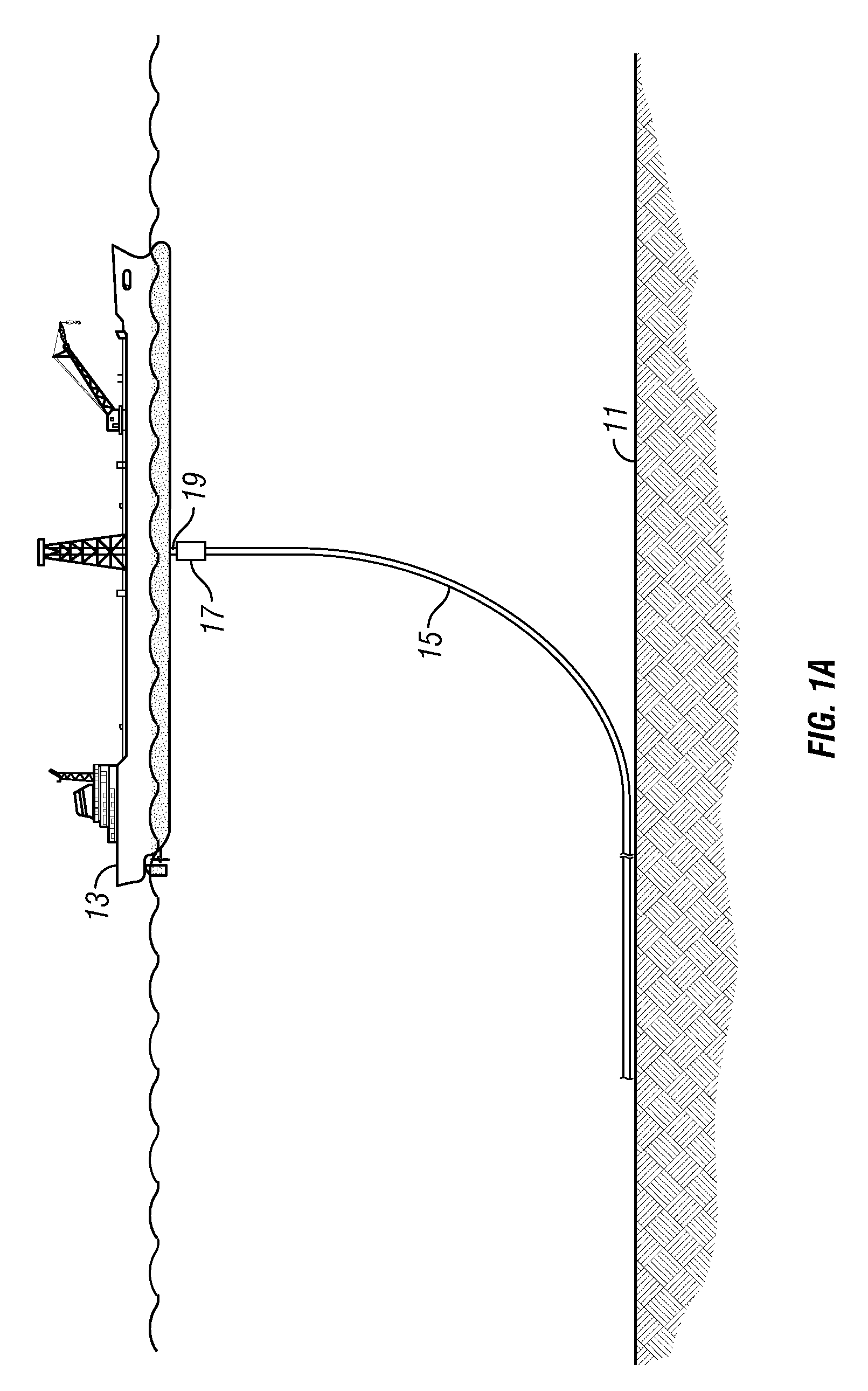
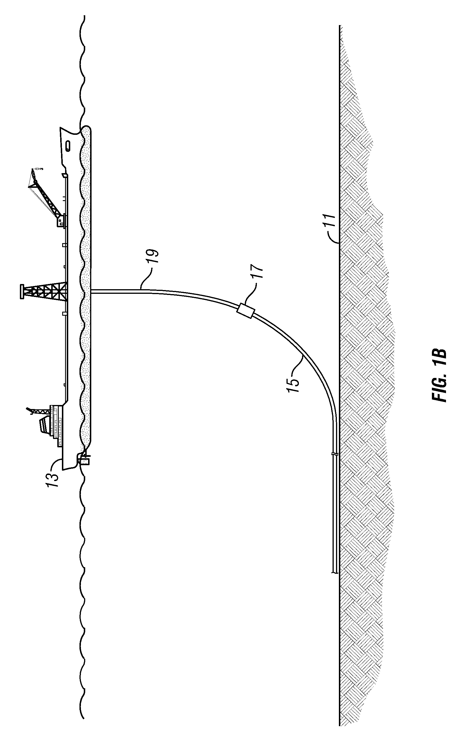
[0032]Referring to FIGS. 1A-1E, a method is illustrated for installing a subsea flowline and riser assembly 10 (FIG. 1E) on a sea floor 11 according to one embodiment of the present invention. In the preferred embodiment, an installation vessel 13 sails to a predetermined location to begin the installation of subsea flowline and riser assembly 10. While vessel 13 is illustrated as a “J-Lay” vessel, vessel 13 can also be an “S-lay” vessel or a “REEL” vessel for the installation of subsea flowline and riser assembly 10 pursuant the various methods described herein.

[0033]Vessel 13 lowers a first end portion of a flowline 15 to sea floor 11. This can be in accordance with standard practices, in which a plurality of segments of flowline 15 are each welded to a previous segment which is about to be lowered into the sea in order to form a single flowline of a desired length. The flowline installation begins with a predetermined target area and ends in a predetermined target area. As will b...


PUM


Abstract

A method for installing a subsea flowline and riser assembly on a sea floor includes providing a flowline having an axis and an end connected to a hinge-over joint, and a riser having an axis and an end connected to the joint such that the axes of the riser and flowline extend substantially parallel. An end of the flowline opposite the joint is lowered to the sea floor. The end of the flowline connected to the joint is lowered to the sea floor. The joint is connected to a foundation that is installed in the sea floor. The riser is rotated about the hinge-over joint such that the riser axis is substantially perpendicular to the flowline axis. A subsea jumper is connected between an opening formed in the flowline and an opening formed in the riser so that the riser is in fluid communication with the flowline.

Description

FIELD OF THE INVENTION[0001]This invention relates in general to the conveyance of hydrocarbons from a subsea well or wells, and in particular to an apparatus and assembly, and methods associated therewith, for conveying the hydrocarbons from a subsea flowline to a floating production unit or vessel at the surface.BACKGROUND OF THE INVENTION[0002]When conveying hydrocarbons from a subsea well to a vessel at the surface, the hydrocarbons are often communicated through flowlines and risers extending along the surface of the sea floor. The flowline is the part resting on the sea floor and the riser is the piece that connects the flowline to the floating production unit or vessel at the surface. The flowline can be extending from a single subsea wellhead, from subsea processing equipment, or from a subsea collection manifold.[0003]In one previous arrangement, a steel catenary riser (SCR) is an extension of the flowline or pipeline from the sea floor to a hang-off location in the floatin...

Claims


Application Information

Patent Timeline
IPC IPC(8): E21B7/12
CPCE21B17/01
Inventor CRITSINELIS, ANTONIO C. F.
Owner CHEVROU USA INC
Learn More