
Frameless switched reluctance motor and application as a top drive for a rotary pump

a rotary pump and switch-reluctance technology, which is applied in the direction of piston pumps, magnetic circuit shapes/forms/construction, borehole/well accessories, etc., can solve the problems of dangerous damage to the top drive and motor, the case is not adequately served with the prior art top drive, and the low rotational speed is not currently practiced. , to achieve the effect of reliable operation

Inactive Publication Date: 2005-12-08
MSI MACHINEERING SOLUTIONS
View PDF12 Cites 31 Cited by
  • Summary
  • Abstract
  • Description
  • Claims
  • Application Information

AI Technical Summary

Benefits of technology

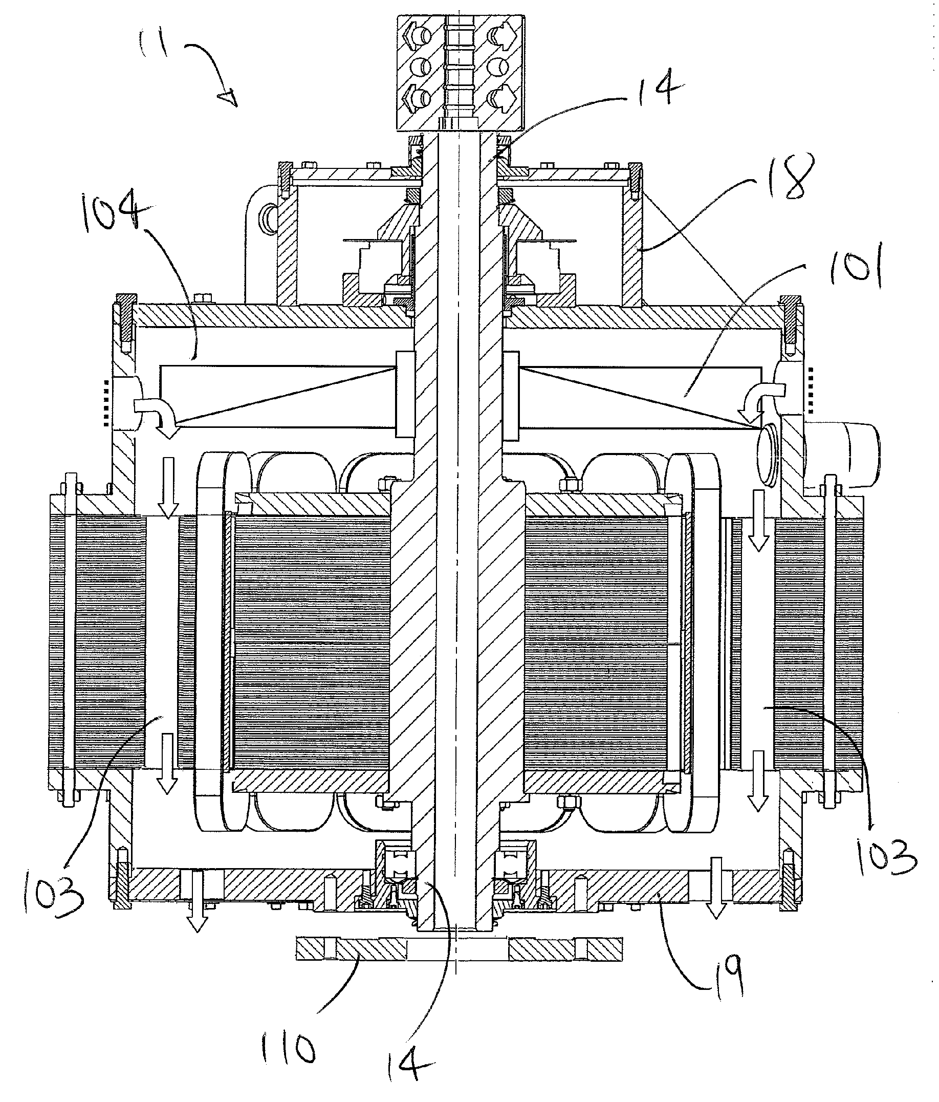
[0013] In one embodiment, induced heat, which can build up and cause premature failure of conventional SRM technology under such rigorous operating conditions, is effectively dissipated under another embodiment of the improved top drive. In this preferred embodiment, ambient air is circulated from outside the motor, into the motor and across the stator, stator coils and rotor. In one preferred embodiment, the stator is manufactured having a radially extending outer profile, such as a square, the periphery of which is fit with axial air passages. An air mover conducts air axially through the air passages for cooling the stator.
[0030] Low Maintenance: The improved top drive concentric design simplifies installation and set-up time. There are no belts to tighten or adjust, only periodic check of the upper bearing oil level and annual re-greasing of the bottom bearing.

Problems solved by technology

Lower rotational speeds are not currently practiced due to the large gear reduction required and lack of flexibility to attain greater speeds as pumping conditions improve.
These cases are not adequately served with the prior art top drives.
If unrestrained, backspin speed of the rods can reach upwards of 5,000 rpm and, in combination with gear reduction to the top drive (now acting as a speed increaser), the resulting speed at the top drive and motor can dangerously destructive—with most injuries being caused by sheave self-destruction.
Braking shoes, drums, shoes, pads and discs are subject to wear and the possibility of localized hot spots which can be an ignition hazard.
At the high torque of backspin conditions, the hydraulic fluid can become very hot, or if the fluid is lost, backspin control is also lost.
Slip associated with AC induction motor unfortunately limits the motor's ability to reach the low rotational speeds desired in some circumstances, such as with high viscosity oils.
Low rotational speeds can result in motor overheating.
Further, to start an AC induction motor under load can result in in-rush amperage as much as 5 or 6 times the normal full load operating current.
While this is only for a short period of time and is an accepted disadvantage of AC motors, there is a further economic impact.

Method used


Image

  • Frameless switched reluctance motor and application as a top drive for a rotary pump
  • Frameless switched reluctance motor and application as a top drive for a rotary pump
  • Frameless switched reluctance motor and application as a top drive for a rotary pump

Examples


embodiment a

Cooling Embodiment A

[0083] Induced heat, which can build up and cause premature failure of conventional SRM technology under such rigorous operating conditions, is effectively dissipated under another embodiment of the improved top drive 1. In this preferred embodiment, ambient air is circulated from outside the SRM 11, into the motor and across the stator 12 and rotor 13.

[0084] With reference to FIG. 6-24, the flow path of the cooling air is through cooling air passages formed through a combination of unique stator and rotor design features.

[0085] Simplistically, air is conducted through passages in the stator 12 or laminate stack to remove heat generated by the motor. The air can be directed axially through the stator or radially therethrough.

[0086] In one embodiment, the air is directed upwardly through spaces between adjacent coils wound on adjacent stator poles and through an array of axially-extending passages formed in the rotor 13. With reference to FIGS. 11 and 12, the s...

embodiment b

Cooling Embodiment B

[0090] While the stator 12 may be constructed of low-loss or loss-less material to minimize heat generation, excessive heat may yet result. In this embodiment, a combination of low-loss electrical steel, a modified cross-section for the stator having cooling passages, and forced-cooling is implemented.

[0091] With reference to FIGS. 25 and 26, a stator for the SRM can optionally comprise a laminate stack of rectangular electrical steel. Preferably, heating due to energy loss in the magnetization cycles is minimized through the use of non-oriented, high silica electrical steels such as 0.014 inch gauge ASTM 36F155 / AISI 29 M19. The nominal properties of M19 electrical steel includes a maximum core loss Pc of 1.74 W / 1b and resistivity of 45-55 mW cm. This is contrast to conventional motors having 0.025 inch gauge ASTM 64F275 / AISI 24 M25 electrical steel having a maximum core loss Pc of 2.75 W / 1b and resistivity of 20-30 mW cm.

[0092] As shown in FIG. 25 the stator 1...


PUM


Abstract

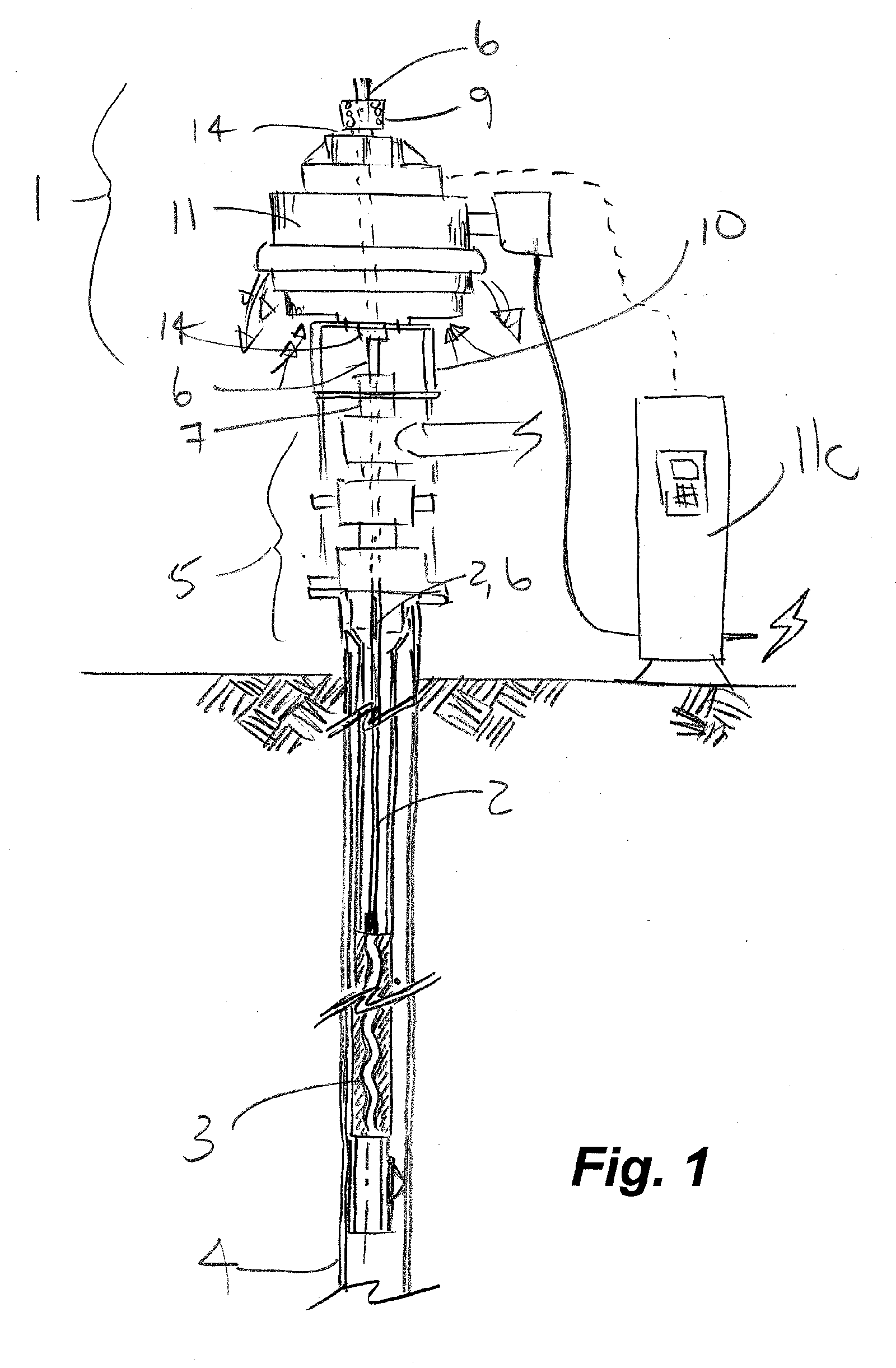
A frameless switched reluctance motor (SRM) has a stator sandwiched between two housings. Axial load on the rotor shaft is directed through a first bearing, through the first housing to the stator and through the second housing to a motor support. Heat is dissipated using low-loss electrical steel, one or more air movers and air passages through the motor. Preferably a stator profile enables the air passages to be formed through the stator's lamination stack. Optionally air is routed through passages between the coils and through air passages along the air gap and radially through passages between an upper and a lower stator. A first self aligning bearing adapts to misalignment between the first housing and the shaft and a second bearing is provided with transverse movement. Preferably, the frameless motor is adapted for support to a wellhead for driving a downhole rotary pump and a rotary rod string.

Description

CROSS REFERENCE TO RELATED APPLICATION [0001] This application is a regular application claiming priority of U.S. Provisional Patent application Ser. No. 60 / 576,577 filed Jun. 4, 2004.FIELD OF THE INVENTION [0002] The invention related to a switched reluctance motor, and the design thereof, which is adapted for supportably rotating a rod string which in turn drives a progressive cavity pump. BACKGROUND OF THE INVENTION [0003] A progressive cavity (“PC”) pump is located in a well and is used to pump subterranean fluids to the surface. Well over 12,000 oil wells in Canada use PC pumps. Conventionally the PC pump is driven from a speed-reducing drivehead or top drive located at the surface. A long assembly or string of rods transmit the slow rotation from the top drive down the well to the PC pump. The top end of the rod string is fitted with a polish rod which is driven through a rod clamp which is driven by the top drive. [0004] The conventional rod string rotational speed of 30-700 ...

Claims


Application Information

Patent Timeline
IPC IPC(8): E21B4/04E21B43/12F04C13/00F04C15/00H02K1/20H02K5/04H02K5/10H02K5/15H02K5/16H02K5/173H02K5/20H02K7/00H02K7/08H02K7/14H02K9/06H02K9/08H02K19/02H02K19/10
CPCE21B43/126H02K1/20H02K5/10H02K5/15H02K5/161H02K19/103H02K5/20H02K7/08H02K7/14H02K9/06H02K5/1732H02K5/207
Inventor TESSIER, LYNN P.DOYLE, JOHN P.WEBER, JAMES L.
Owner MSI MACHINEERING SOLUTIONS
Learn More