
Polymerization process

a polymerization process and gas phase technology, applied in the field of gas phase polymerization process, can solve the problems of ineffective operation of various reactor systems, difficult to meet the needs of gas phase process, and new challenges, and achieve the effect of improving the efficiency of the gas phase process

Active Publication Date: 2005-12-01
EXXONMOBIL CHEM PAT INC
View PDF32 Cites 81 Cited by
  • Summary
  • Abstract
  • Description
  • Claims
  • Application Information

AI Technical Summary

Benefits of technology

[0242] In order to provide a better understanding of the present invention including representative advantages thereof, the following examples are offered.

Problems solved by technology

Regardless of these technological advances in the polyolefin industry, common problems, as well as new challenges still exist.
For example, the tendency for a gas phase process to foul and / or sheet remains a challenge, which can particularly be dependent on the polymer being produced and the catalyst system employed.
Fouling, sheeting and / or static generation in a continuous gas phase process, in for example heat exchangers, distributor plates, and probes, can lead to the ineffective operation of various reactor systems.
In a typical continuous gas phase process, a recycle system is employed for many reasons including the removal of heat generated in the process by the polymerization reaction, and recycle processes offer many opportunities for fouling.
However, application of the technology is expensive and requires substantial investment in powder handling equipment in the production plant.
Sticky, or cohesive polymer causes a range of problems in the gas phase reactor systems.
For example, sticky polymer can reduce the quality of fluidization that occurs within the reactor, and can reduce the degree of internal mixing below the minimum levels required to disperse the catalyst and maintain stable temperature control.
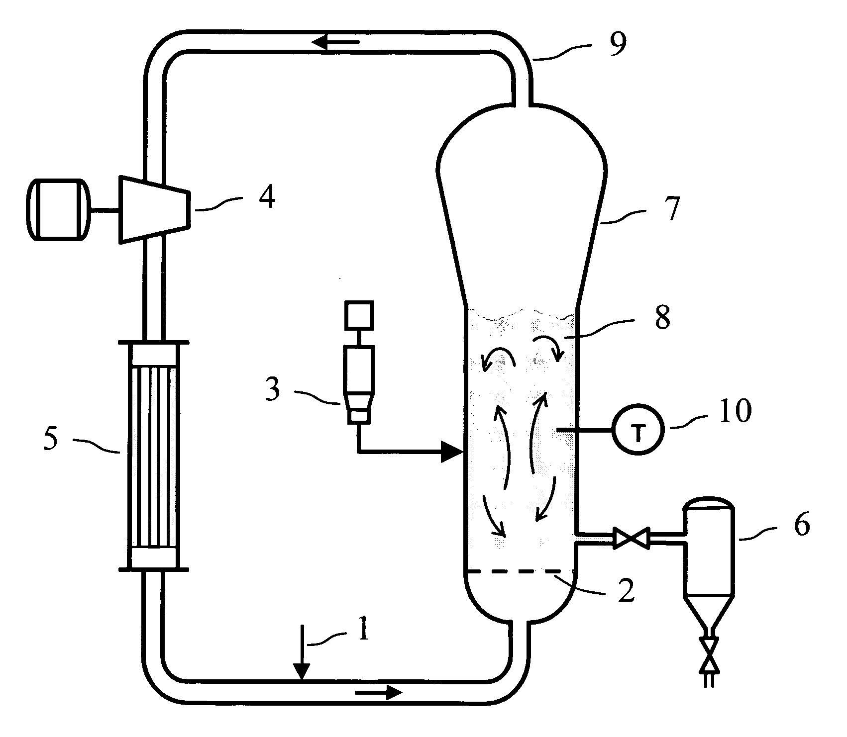
In addition, stickiness of the polymer can lead to the deposition of polymer product on the walls of the reactor expanded section, which often leads to the formation of dome sheets (solid masses of polymer material deposited on the walls of the “dome”, or expanded section of the reactor) In many cases, these dome sheets are large and massive, containing as much as 100 kg of agglomerated polymer.
These dome sheets eventually fall from the dome and become lodged on the distributor plate, where they interfere with fluidization.
In some cases, the dome sheets block the product discharge port, and force a reactor shut-down for cleaning.
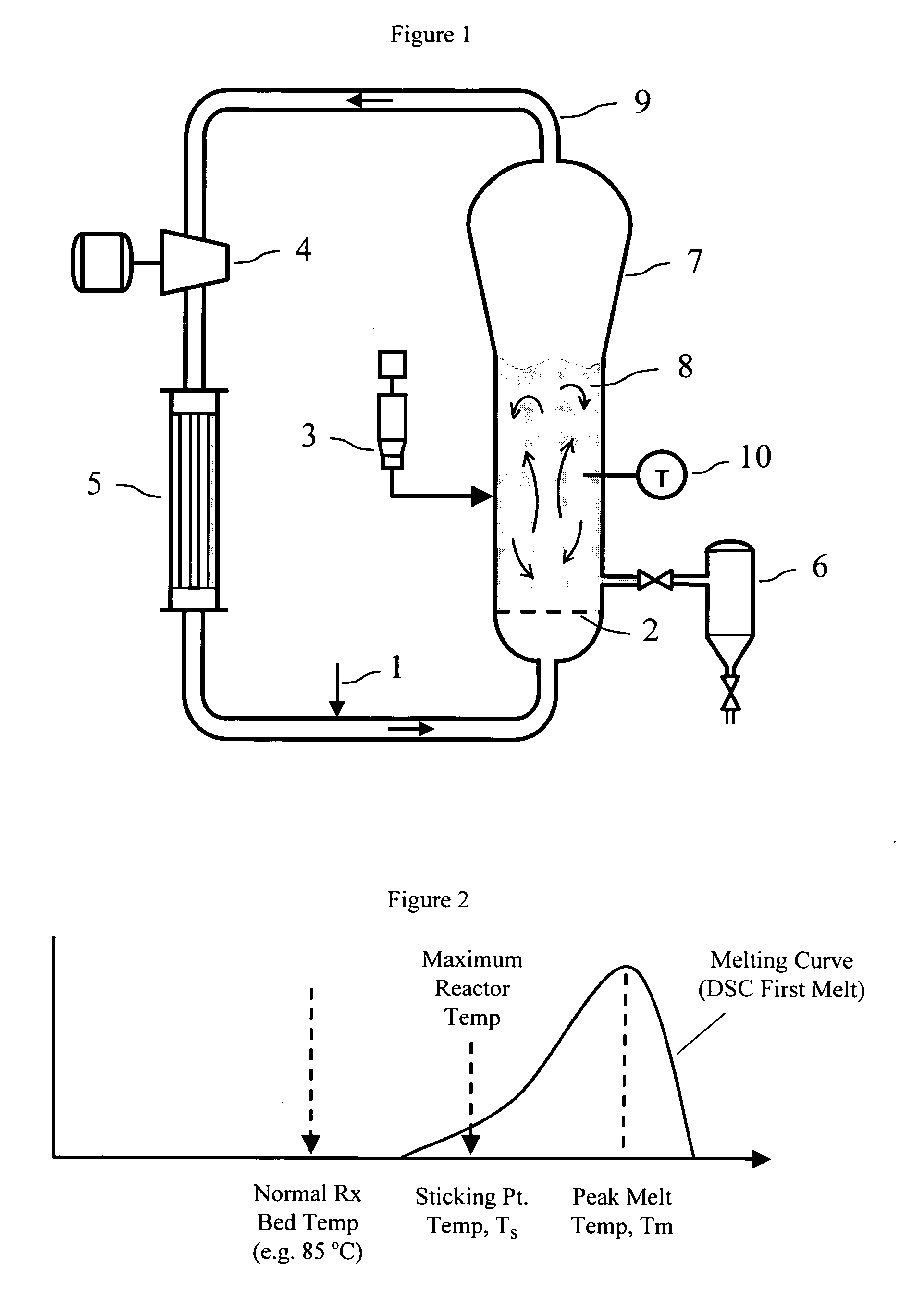
Our findings indicate that, in many cases, the operating temperatures are too high relative to the polymer sticking temperature.

Method used


Image

  • Polymerization process
  • Polymerization process

Examples


examples

[0242] In order to provide a better understanding of the present invention including representative advantages thereof, the following examples are offered.

[0243] Density was measured in accordance with ASTM-D-1505-98

[0244] Melt Index (MI), 121 and 12 were measured by ASTM D 1238-01. DSC Peak melting point was measured as follows: 3 to 9 milligrams of granular polymer sample was charged into a 30 microliter, aluminum, hermetically sealed capsule (Perkin Elmer part Number B0182901), weighed, and placed on the test stage of a DSC instrument. As is standard practice in the DSC technique, a blank capsule was also placed on the reference stage. (If the test was to be done in the presence of liquid, the test capsule was also charged with the liquid prior to closing, or sealing, the capsule.) The DSC instrument was programmed to start each test by first ramping down the temperature (of both capsules) at a rate of 5° C. / min until reaching 0° C., and holding at this temperature for 2 minute...

examples 1-3

[0249] A series of tests were performed on polymer samples to determine the Critical Temperatures for selected polymer solvent combinations.

[0250] In the following examples, the dry sticking temperature was measured by one or both of two methods. The first method involved fluidizing the polymer sample in a medium scale fluidized bed reactor system. (This method is referred to as the medium scale fluidization test). Tests conducted by this method were performed in a fluidized bed reactor equipped with a temperature control system, a differential pressure cell to monitor the polymer bed weight and quality of fluidization, and a GC analyzer for monitoring the gas composition. The reactor consisted of a cylindrical bed section of 15.2 cm diameter and 117 cm height, with a conical expanded section increasing to 25.4 cm diameter at the top of the reactor. Gas entered the fluidized bed through a perforated distributor plate. For each test, the unit was charged with approximately 2500 gram...

example 1

[0253] In this example the critical temperature was determined for a commercial grade linear low density polyethylene sample produced from a conventional-type transition metal catalyst as described in Example A (below) with a hexene comonomer. The polymer 12 was 0.768 dg / min and the molded density was 0.9173 g / cc. The peak DSC melting point for the dry polymer was 125° C. and the melting point depression was measured as 18° C., 21° C., and 2° C. for isobutane, isopentane, and HFC-245fa, respectively. The polymer dry sticking temperature was determined to be 104° C. in both the medium scale fluidization test and lab scale fluidization test. In the medium scale fluidization test there was no indication from the differential bed pressure cell that quality fluidization was lost anytime during the temperature ramp-up; however, visual inspection of the reactor internals following the test showed polymer aggregates caked on the reactor walls approximately 0.5 cm thick. As calculated from t...


PUM

PropertyMeasurementUnit
Temperatureaaaaaaaaaa

Abstract

The present invention relates to a continuous gas phase process comprising polymerizing one or more hydrocarbon monomer(s) in a fluidized bed reactor in the presence of catalyst system or polymerization catalyst and a condensable fluid for a period of at least 12 hours where the bed temperature is less than the Critical Temperature and the dew point temperature of the gas composition in the reactor is within 25° C. of the bed temperature.

Description

PRIORITY [0001] This invention claims the benefit of provisional applications U.S. Ser. No. 60 / 572,876, filed May 20, 2004, U.S. Ser. No. 60 / 572,786, filed May 20, 2004 and U.S. Ser. No. 60 / 581,463, filed Jun. 21, 2004.FIELD OF THE INVENTION [0002] The present invention relates to a gas phase polymerization process operating below the Critical Temperature. BACKGROUND OF THE INVENTION [0003] Advances in polymerization and catalysis have resulted in the capability to produce many new polymers having improved physical and chemical properties useful in a wide variety of superior products and applications. With the development of new catalysts, the choice of polymerization-type (solution, slurry, high pressure or gas phase) for producing a particular polymer has been greatly expanded. Also, advances in polymerization technology have provided more efficient, highly productive and economically enhanced processes. Regardless of these technological advances in the polyolefin industry, common...

Claims


Application Information

Patent Timeline
IPC IPC(8): C08F2/00C08F10/02C08F210/16
CPCC08F210/16Y10S526/901C08F2/34C08F2/005C08F210/14C08F2500/12C08F4/64C08F10/00
Inventor HAGERTY, ROBERT O.STAVENS, KEVIN B.DECHELLIS, MARC L.FISCHBUCH, BRETT D.FARLEY, JAMES M.
Owner EXXONMOBIL CHEM PAT INC
Learn More