
Open-loop start-up method for a resonating device

a resonating device and open-loop technology, applied in the field of open-loop start-up methods for resonating devices, can solve the problems of increasing the cost of mass producing tuning fork resonating devices, affecting the production efficiency of resonating devices, so as to facilitate the generation of resonating output signals

Inactive Publication Date: 2005-12-01
TEMIC AUTOMOTIVE OF NORTH AMERICA
View PDF13 Cites 14 Cited by
  • Summary
  • Abstract
  • Description
  • Claims
  • Application Information

AI Technical Summary

Benefits of technology

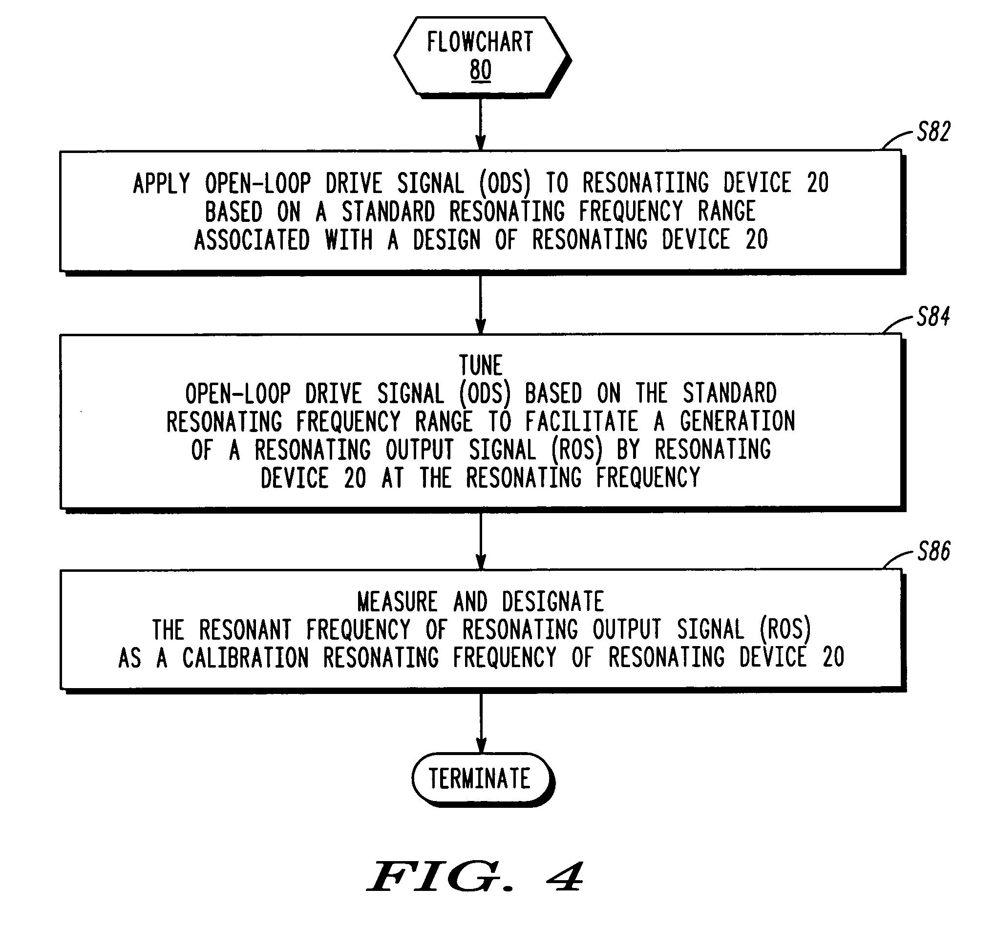
[0010] A seventh form of the present invention is a method involving an application of an open-loop drive signal to the resonating device based on the calibration resonant frequency, a tuning of the open-loop drive signal based on a calibration frequency range defined by the calibration resonant frequency to facilitate a generation of a resonating output signal by the resonating device, and an application of a closed-loop drive signal to the resonating device subsequent to the generation of the resonating output signal by the resonating device at the resonant frequency.

Problems solved by technology

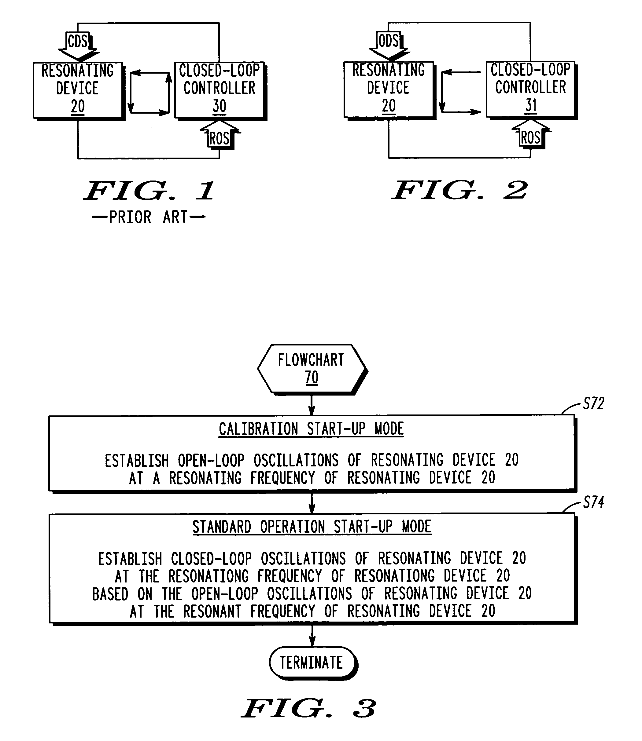
A drawback of this closed-loop start-up method is a requirement of a wide spectrum and large amplitude of closed-loop drive signal CDS as well as a feedback circuit within closed loop controller 30 that is carefully tuned to resonating device 20.
This poses restrictive limitations on manufacturing parameters of resonating devices and increases cost of mass producing tuning fork resonating devices, particularly in view of the fact that unavoidable variations in known processes for manufacturing resonating devices result in difference in the resonant frequencies in a significant number of the resonating devices.

Method used


Image

  • Open-loop start-up method for a resonating device
  • Open-loop start-up method for a resonating device
  • Open-loop start-up method for a resonating device

Examples


Embodiment Construction

[0028]FIG. 3 illustrates a flowchart 70 representative of a method for starting-up resonating device 20 (FIG. 1). A calibration start-up mode of a stage S72 of flowchart 70 and a standard operation start-up mode of a stage S74 of flowchart 70 are sequentially implemented during an initial execution of flowchart 70 for resonating device 20. Thereafter, calibration start-up mode of stage S72 of flowchart 70 may be omitted during subsequent executions of flowchart 70, particularly when the calibration start-up mode of stage S72 is performed in a factory setting prior to a commercial use or sale of the present invention.

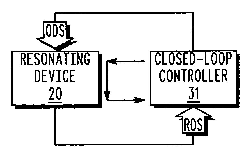
[0029] The calibration start-up mode of stage S72 involves an establishment, as illustrated in FIG. 2, by an open-loop controller 31 of open-loop oscillations of resonating device 20 at its resonating frequency. In practice, the acts for implementing stage S72 are dependent upon the design of resonating device 20 and the design of open-loop controller 31, and are theref...


PUM


Abstract

A system employing a resonating device and a controller implements a method involving an establishment by the controller of open-loop oscillations of the resonating device at a resonating frequency of the resonating device, and an establishment by the controller of closed-loop oscillations of the resonating device based on the open-loop oscillations of the resonating device at the resonating frequency. To this end, the controller controls an application and a tuning of a first open-loop drive signal to the resonating device based on a design-drive standard resonating frequency range whereby the controller can measure and designate a frequency of a resonating output signal from the resonating device as a calibration resonant frequency, and controls an application and a tuning of a second open-loop drive signal to the resonating device based on the calibration resonant frequency whereby the controller can subsequently apply a closed-loop drive signal to the resonating device.

Description

FIELD OF THE INVENTION [0001] The present invention generally relates to start-up methods for resonating devices. More specifically, the present invention relates to an open-loop method for a fast and reliable start-up of a gyroscopic sensor. BACKGROUND OF THE INVENTION [0002]FIG. 1 illustrates a closed-loop resonating system employing a resonating device 20 (e.g., a gyroscopic sensor) that needs to be operated at its resonant frequency by a closed-loop controller 30 to thereby provide a useful resonating output signal. To this end, start-up methods for resonating device 20 as known in the art rely on noise in closed loop controller 30 to generate a closed-loop drive signal CDS for establishing closed-loop oscillations of resonating device 20 at its resonating frequency to thereby facilitate a generation of a resonating output signal ROS by resonating device 20. Resonating output signal ROS is used as a feedback to closed-loop drive signal CDS via closed loop controller 30 to stabil...

Claims


Application Information

Patent Timeline
IPC IPC(8): G01C19/56G01P9/04H03B5/06
CPCH03B5/06
Inventor ZIVANOVIC, STEVANROBER, STEPHEN J.
Owner TEMIC AUTOMOTIVE OF NORTH AMERICA
Learn More