Eureka AIR delivers breakthrough ideas for toughest innovation challenges, trusted by R&D personnel around the world.

Mini case for computer

a computer and mini-case technology, applied in the field of mini-cases for computers, can solve the problems of difficult assembly, inconvenient carrying, complex wiring, etc., and achieve the effect of convenient assembly, small volume, and convenient carrying

Inactive Publication Date: 2005-11-24
LIN SHU FEN
View PDF4 Cites 14 Cited by
  • Summary
  • Abstract
  • Description
  • Claims
  • Application Information

AI Technical Summary

Benefits of technology

[0005] The present invention relates to an improved case, which is small in volume, convenient in carrying, easy in assembling, simple in wiring, convenient for not plugging in from rear, and good in heat transmission.

Problems solved by technology

Common deficiencies in conventional cases include (1) large in volume; (2) inconvenient in carrying; (3) difficult in assembling; (4) complex in wiring; (5) high in cost; (6) inconvenient for plugging in from the rear; (7) bad in heat transmission.

Method used


Image

  • Mini case for computer
  • Mini case for computer
  • Mini case for computer

Examples


Embodiment Construction

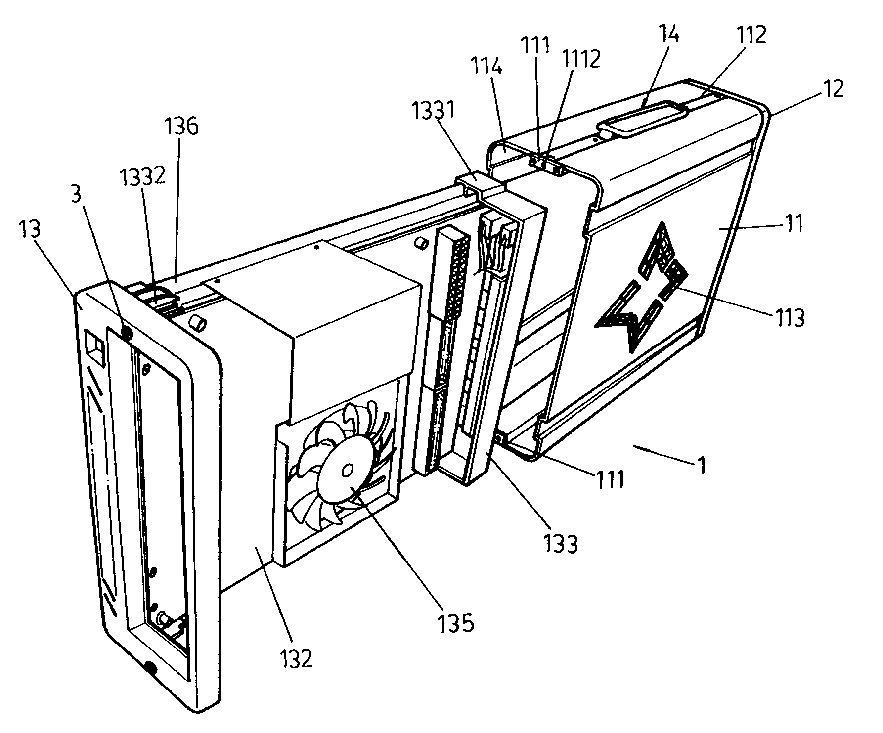
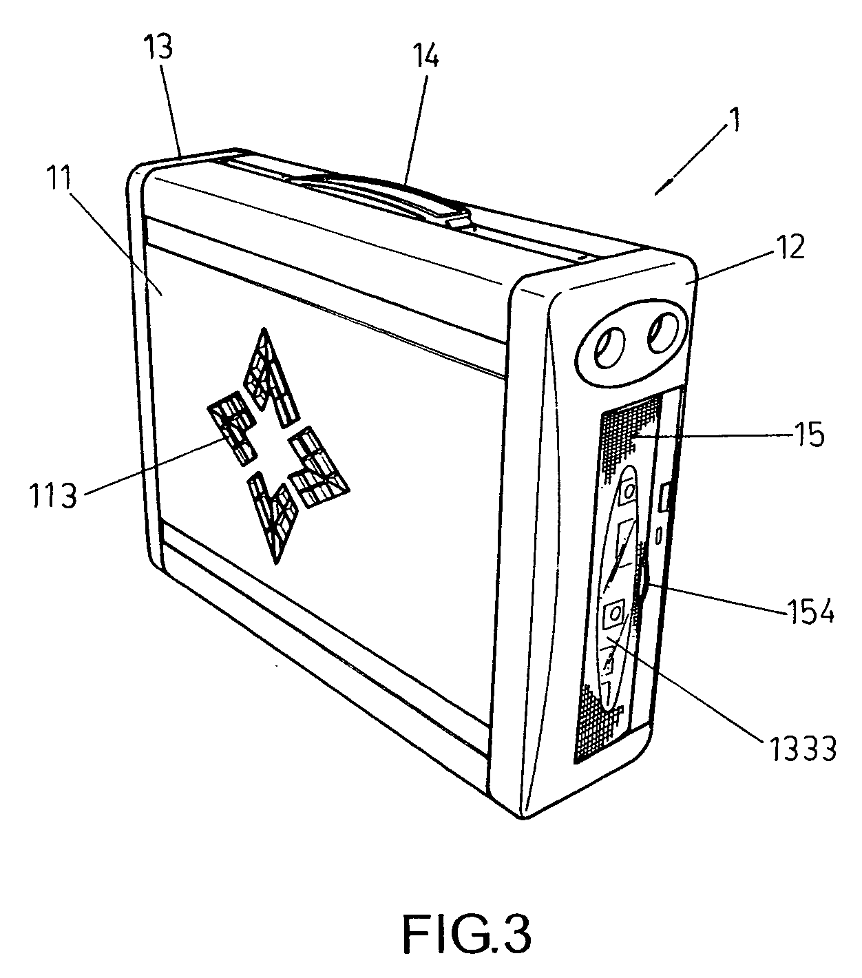
[0021] Referring to FIGS. 3˜4. The present invention is a mini case 1 comprising a front panel 12, a rear panel 13, supporting frames 136, a case 11, and a handle set 14.

[0022] Referring to FIGS. 4 and 9 / 10. The case 11 is formed enclosing the whole computer element, wherein on a lateral a ventilation opening 113 formed. On a top and a bottom of the case 11, a groove 112 formed, wherein two screwed holes 1122 formed on each end, with two screws 3 penetrating through holes 1111 to fasten a locking plate 111 thereof on each end.

[0023] Referring to FIGS. 4 and 5. Two supporting frames 136, made of Aluminum to enhance heat transmission, formed inside the case 11 as a fixture for directly securing parts and a circuit board 132 thereon without a bottom plate. A fan 135 formed right behind the ventilation opening 113 to blow heat out of the circuit board 132. Supporting frames 136, with guiding blocks 1331 and 1332 formed thereof, can be guided through a space 114 and fixed in the case 1...


PUM


Abstract

The present invention relates to an improved case for a computer, which is small in volume, convenient in carrying, easy in assembly, simply in wiring, low in cost, convenient for plugging in from the front, and good in heat transmission. Its peculiar structure includes a front panel, a rear panel, support frames, a case, and a handle, wherein, an ventilation opening formed on Aluminum supporting frames; a front panel and a rear panel each secured by a locking plate to supporting frames; a circuit board formed on supporting frames without a bottom plate; an anti-dust cover, with sockets connecting with the circuit board, formed in a front; and a retractable handle, being fixed on a fastener, formed on a groove atop a case. Thereby, the present invention is both advanced and pragmatic in enhancing operation.

Description

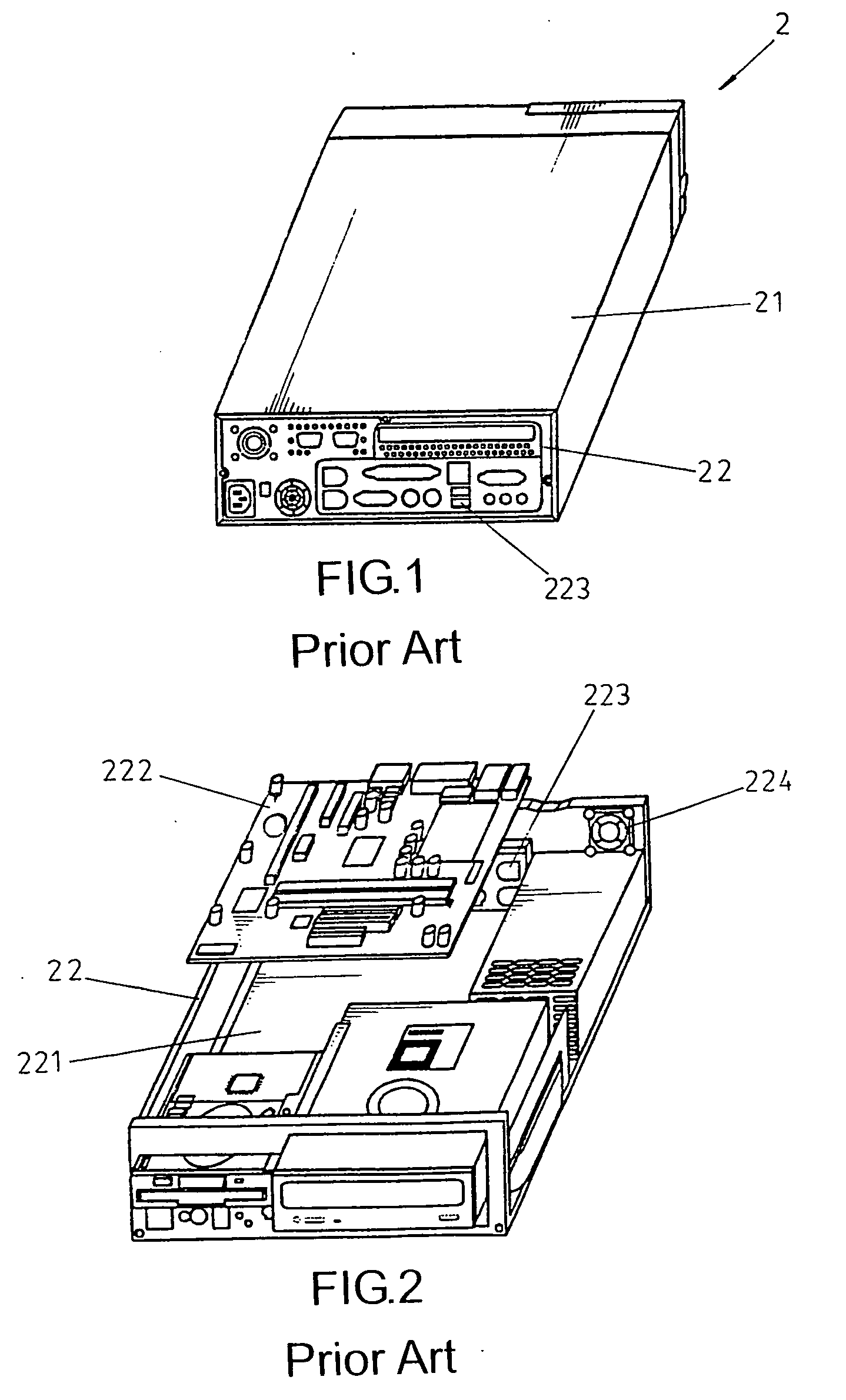
BACKGROUND OF THE INVENTION [0001] (a) Field of the Invention [0002] The present invention relates to a mini case for a computer. Its peculiar structure is formed by a retractable handle, an ventilation opening formed on a case, a circuit board secured on a supporting frame without a bottom plate, sockets formed in the front, an anti-dust cover formed in the front, and a front panel and a rear panel each secured by a locking plate to the supporting frame. [0003] (B) Description of the Prior Art [0004] Referring to FIGS. 1 and 2. A conventional product includes a computer 2, a case 21, and a supporting frame 22, wherein sockets 223 and a fan 224 formed behind. To place a circuit board 222, a bottom plate formed underneath the inner frame 22. Common deficiencies in conventional cases include (1) large in volume; (2) inconvenient in carrying; (3) difficult in assembling; (4) complex in wiring; (5) high in cost; (6) inconvenient for plugging in from the rear; (7) bad in heat transmissio...

Claims


Application Information

Patent Timeline
Patent Type & Authority Applications(United States)
IPC IPC(8): G06F1/16G06F1/18H05K5/00
CPCG06F1/1613G06F1/1656G06F1/183G06F1/181G06F1/18
Inventor LIN, SHU-FEN
Owner LIN SHU FEN
Why Eureka
Eureka Blog
Learn More