
Chiral temperature gradient focusing

Inactive Publication Date: 2005-11-24
GOVERNMENT OF THE UNITED STATES AS REPRESENTED BY THE SEC OF COMMERCE THE NAT INST OF STANDARDS & TECH
View PDF1 Cites 13 Cited by
  • Summary
  • Abstract
  • Description
  • Claims
  • Application Information

AI Technical Summary

Benefits of technology

[0031] An additional advantage of the present invention for the separation of the stereoisomers of a chiral material is that it is very easy to reverse the positional order of the focused peaks corresponding to the different stereoisomers. This can be done simply by reversing the direction of the temperature gradient, the sign of the applied electric field, and the direction of the bulk fluid flow. As mentioned above, this can be beneficial for the analysis of the purity of chiral materials that are desired to contain only one stereoisomer.
[0032] Further features and advantages of the present invention will be set forth in, or apparent from, the detailed description of preferred embodiments thereof which follows.

Problems solved by technology

One disadvantage with prior microfluidic devices is that there is frequently a mismatch between the extremely small quantities of sample material used for analysis and the often much larger quantities needed for loading the material into the microfluidic device and transporting it to the point of analysis.
One major drawback to electric field gradient focusing is that the device tends to be difficult to construct and that it requires the control of voltage on an additional electrode, e.g. 4 of FIG. 1(a), that is used to apply the electric field gradient.
In addition, if electrodes are used to generate electric field gradients, unwanted chemical products will be generated electrochemically at the fluid-electrode interface.
One disadvantage of isoelectric focusing is that it is limited in application because it can only be used with materials having an accessible isoelectric point.
Additionally, the concentration to which a protein can be focused with isoelectric focusing is severely limited due to the low solubility of most proteins at their isoelectric points.
The major limitation of chiral capillary electrophoresis and of capillary electrophoresis in general is its poor detection limits, which are typically too high for the analysis of chiral compounds, e.g., drugs and drug metabolites in body fluids such as serum or urine.
However, these techniques are limited in their applicability because the chiral materials or molecules to be focused must be chemically derivatized so that 1) they have an isoelectric point, and 2) the isoelectric point is dependant on the degree of interaction with a chiral selector.
Furthermore, most pharmaceutical molecules would not be amenable to the kind of chemical derivatization required for isoelectric focusing, see, e.g., Ogle, D.; Ho, A.; Gibson, T.; Rylatt, D.; Shave, E.; Lim, P.; Vigh, G.

Method used


Image

  • Chiral temperature gradient focusing
  • Chiral temperature gradient focusing
  • Chiral temperature gradient focusing

Examples


Embodiment Construction

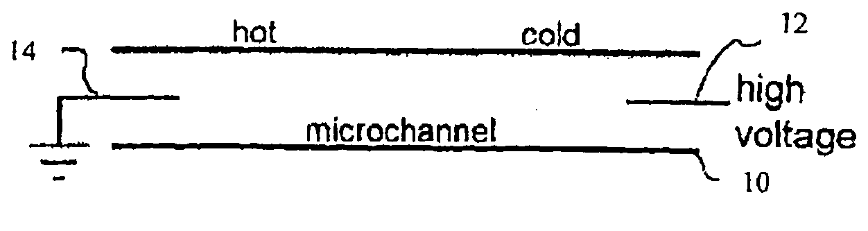
[0042] A material can be focused in a fluid conduit such as a channel or capillary when its total velocity is in opposite directions in different portions of the conduit, so that the material will move into the middle of the conduit and stop at a position where its velocity is zero. One way of accomplishing this is to cause the material to move with an electrophoretic velocity that varies along the length of the conduit. This can be accomplished by producing an electrophoretic velocity gradient along the conduit. If an electrophoretic velocity gradient is established, but the electrophoretic velocity is still in the same direction along the entire length of the conduit, a counter-balancing bulk flow can be applied to the fluid in the conduit, driven either by electroosmosis, pressure gradients, or both, so that the total velocity of the material, i.e., the vector sum of the bulk flow velocity and electrophoretic velocity of the material is equal to zero at some position along the co...


PUM

PropertyMeasurementUnit
Lengthaaaaaaaaaa
Temperatureaaaaaaaaaa
Pressureaaaaaaaaaa

Abstract

A method and device are provided for concentrating and separating materials in fluids within a fluidic device having a fluid conduit such as a channel or capillary. The concentration is achieved by balancing the electrophoretic velocity of a material against the bulk flow of fluid in the presence of a temperature gradient. An additive is added to the fluid which interacts with the material and which modifies the normal electrophoretic mobility of the material. Using an appropriate fluid, the temperature gradient can generate a corresponding gradient in the electrophoretic velocity so that the electrophoretic and bulk velocities sum to zero at a unique position along the conduit and the material will be focused at that position. The method and device may be adapted for use with a variety of materials including fluorescent dyes, amino acids, proteins, DNA and to concentrate a dilute material.

Description

CROSS-REFERENCE TO RELATED APPLICATIONS [0001] This application is a continuation-in-part of U.S. patent application Ser. No. 10 / 197,331 filed on Jul. 18, 2002 which claims benefit of the filing date of both co-pending Provisional Patent Application Nos. 60 / 307,691, filed on Jul. 25, 2001, and 60 / 323,404, filed on Sep. 19, 2001 and this application also claims benefit of the filing date of Provisional Patent Application No. 60 / 544,126 filed on Feb. 12, 2004.STATEMENT REGARDING FEDERALLY SPONSORED RESEARCH [0002] This invention was made by employees of the United States Government and may be manufactured and used by or for the Government for governmental purposes without the payment of any royalties.FIELD OF THE INVENTION [0003] The present invention relates to a method for electrokinetic focusing of materials in a fluid, and in particular, methods for electro-focusing materials in fluidic devices using electric field gradients. BACKGROUND OF THE INVENTION [0004] Over the past decade...

Claims


Application Information

Patent Timeline
IPC IPC(8): G01N27/447G01N27/453
CPCG01N27/44795G01N27/44734
Inventor ROSS, DAVID J.VREELAND, WYATT N.BALSS, KARIN M.
Owner GOVERNMENT OF THE UNITED STATES AS REPRESENTED BY THE SEC OF COMMERCE THE NAT INST OF STANDARDS & TECH
Learn More