
System and a method for detecting, locating and discerning an approach towards a linear installation

a linear installation and system technology, applied in the field of warning systems, can solve problems such as supply shortages, large and uncontrollable damage, and cut off of fuel sources

Inactive Publication Date: 2005-11-10
MAGAL SECURITY SYST LTD
View PDF15 Cites 27 Cited by
  • Summary
  • Abstract
  • Description
  • Claims
  • Application Information

AI Technical Summary

Benefits of technology

[0031] In a different and additional aspect of the invention—the subject matter of this application, a general method of detection, localizing and identification of an occurrence is presented. In this aspect—the occurrence is an act of a suspicious approach towards a linear installation. The method—includes the stages of mounting discrete sensor units in an array alongside the length of the linear installation, at a certain distance away of each one from its neighbor; implem

Problems solved by technology

Many linear installations, be it buried ones (for example, piping systems) or above the ground ones (for example, railway tracks, fences along borders), constitute potential targets for sabotage or breaking in through them.
An act of terror or vandalism damaging the line, or intrusion into the pipe line installations (e.g., one of the control stations), can cause huge and uncontrollable damage.
In the fuel line example presented above, sabotage damaging the line might result in cut off of fuel sources at many locations, supply shortages, and even explosions accompanied by injuries or even death of humans as well as sever ecological damage to the environment.
At present, there exists no warning or alarm system suitable for protecting linear installations.
However, when patrolling very long lines, it is definitely impossible to cover the total length of the line at a satisfactory frequency, and this fact increases the motivation of terrorists or other intruders to conduct their malicious operations, as they know that the probability of being detected and apprehended is very low.
Even the deployment of electro optical sensors, for example, video cameras, along the length of the line does not provide an adequate solution.
Those detectors are expensive, exposed to the environment, burglary and vandalism, and require constant maintenance.
Their performance deteriorates under certain detrimental environmental effects such as bad or lowered visibility level (night-time, mist or fog), and they cover very limited sectors and not the entire line.
The system does not identify small scale local illegal pumping or stealing of fuel, nor does it provide exact information regarding the location of the problem area.
They do not provide earlier warning messages indicating the would be intrusion or atrocious deed.
These sensors, however, are similar in results to those of the manned patrol that passes occasionally along the length of the pipelines, and its weakness, as a system is the outcome of its inherent low frequency operation.
However, a warning system based on optical fibers has many drawbacks, some of which are presented herein.
For example, a tractor working in an agricultural plot bordering on the optical fiber might appear as “an occurrence” of an extremely dominant incident that affects the optical fiber at a specific point and “blinds” the system rendering it incapable of detecting additional, simultaneous incidents in other (far away) locations along the line, that might be several orders of magnitude more dangerous than those that were detected.
An additional drawback stems from the susceptibility of the optical fiber to cuts or impacts.
For example, within a sector of say 30 km long, damaging actions might take place unnoticed, “sponsored” by the break in the fiber's continuity.
A different, additional drawback stems from the fact that the optical fiber—due to its own long continuing construction—might be easily uncovered and exposed.
An additional drawback of the cited optical fibers system—serving as means for providing warnings triggered by a person approaching the linear installation, such as for example a buried pipe in the ground from a long time past, is the difficulty to upgrade the linear line in order to deploy the fiber along its length.
Yet another additional drawback associated with a system that is based on indications resulting from exposing the optical fiber to local movements and / or bending is the inability to identify the exact type of the interference.
Finally, at times it is just impossible to obtain the required continuity when deploying the fibers' line, as for example when the pipe line traverses a river or passes over a bridge—where it is exposed to the naked eye, or crossing through a difficult to access wadi or over a boulder / cliff.
It is not sufficient just to detect an interference or noise for providing an effective warning regarding the occurrence of a physical access effort or penetrating action onto or through the linear installation.
Relying on sensing of seismic / acoustic interference and / or noise as an indication to the occurrence of physical access effort and / or penetration action and to the location of this incident, is not an effective one as long as no capability of identification and verification were integrated into the system at a high reliability level that they do not constitute false alarms.
Obviously, routine and innocent activities occurring along the installation line and through the linear system, if they happen to be such that might generate noises or interference, while there is no capability available to identify and verify them and their true nature, might generate false alarm at an undesirable frequency.

Method used


Image

  • System and a method for detecting, locating and discerning an approach towards a linear installation
  • System and a method for detecting, locating and discerning an approach towards a linear installation
  • System and a method for detecting, locating and discerning an approach towards a linear installation

Examples


Embodiment Construction

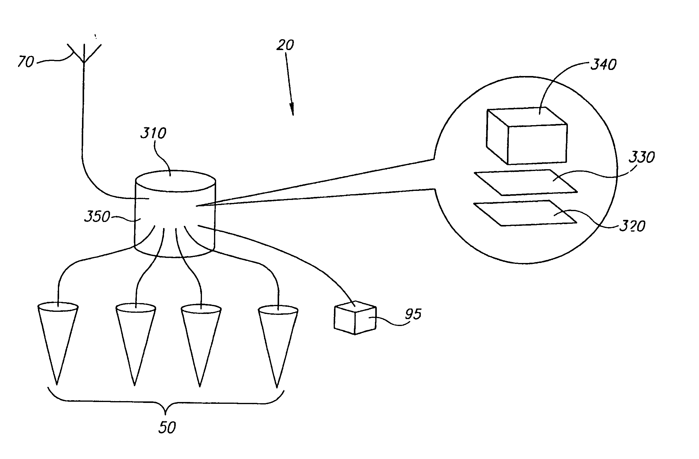
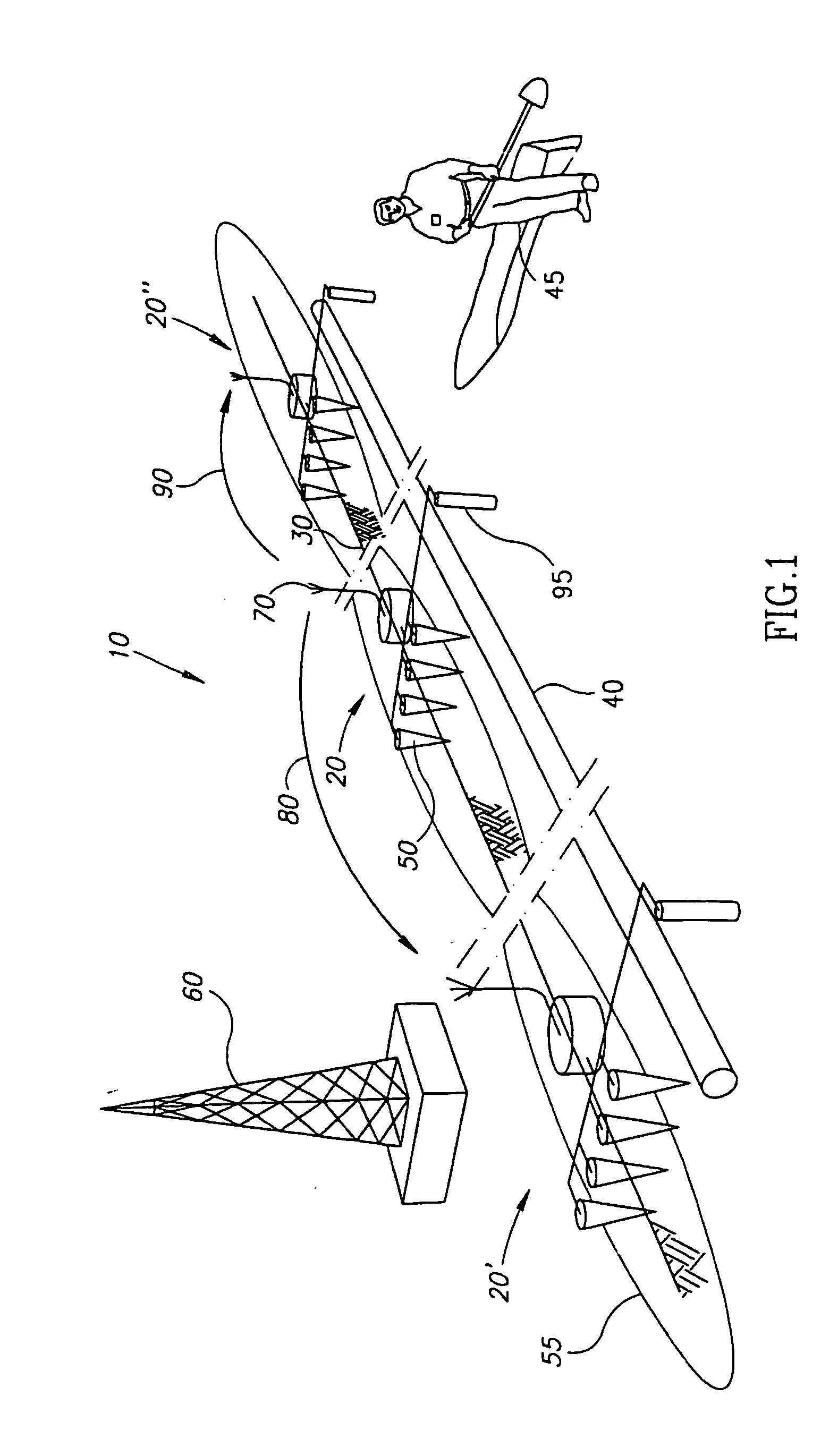
[0041] Referring to FIG. 1, the system 10, whose preferred configuration is described hereinafter, should be viewed and appreciated solely as an example, depicting a sensing unit 20 deployed under the ground level 30 along a fuel pipes' line 40, in order to detect excavation efforts (illustrated as digging effort by intruder 45) or activities towards the pipe.

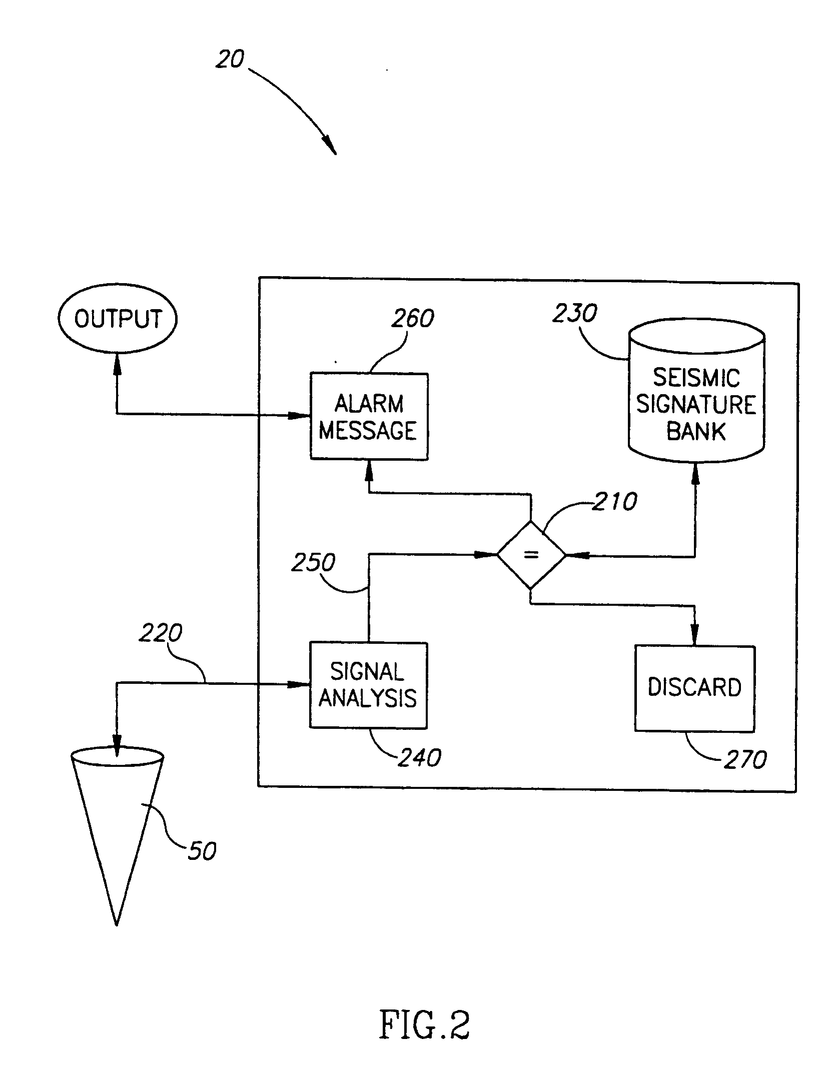
[0042] The system operates by implementing the principle of seismic sensing, and processing of the signals received from the sensors (vibrations detecting geophones 50). The product of the processing is a “typical (characteristic) signature” of the disturbance. This signature is compared, in real time, to a data bank of signatures stored in the system's memory, and if a match is found—through identical correlation level (namely, match) being above a certain given threshold—the system issues a warning sending it to a remote control center 60.

[0043] In order to insure the establishing a good “fix” (namely obtaining an exact rea...


PUM


Abstract

A system and a method for detecting, locating and identifying incidents of approaching a linear installation (e.g.—buried pipe line, railway, fence etc.), that includes plurality of sensing units positions in an array along the length of the linear installation, at a distance one from each other, wherein each unit includes at least one sensor for sensing seismic or acoustic interference or noise / s (in accordance with the configuration of the system, namely either as buried system or as an above the ground one), and the issuance of a suiting indicating signal; a signal processor for analyzing the signal and comparing it to a cache (data bank) of seismic or acoustic interference or noise signatures that is embedded in the sensor unit; and a communications device for transferring data from the sensor unit to a distant command and control center.

Description

CROSS-REFERENCE TO RELATED APPLICATIONS [0001] This application is a continuation of International Application PCT / IL2003 / 000836 filed Oct. 15, 2003, the entire content of which is expressly set forth herein by reference thereto. BACKGROUND [0002] The invention relates to the field of warning systems in general, and to the area of warning systems that protects linear installations, such as piping systems, railway tracks, electricity lines, fences and the like. [0003] Many linear installations, be it buried ones (for example, piping systems) or above the ground ones (for example, railway tracks, fences along borders), constitute potential targets for sabotage or breaking in through them. [0004] For example, in referring to an example that describes a preferred configuration of the present invention, a typical line for conveying fuel is a linear piping system that in most cases is buried in the ground, for example, 16 to 18 inch diameter pipes buried at 1.5 m to 2 m deep below the gro...

Claims


Application Information

Patent Timeline
IPC IPC(8): B61L1/06G01V1/00G08B13/16
CPCB61L1/06B61K9/08G08B13/1663G01V1/001
Inventor ZEHAVI, RON
Owner MAGAL SECURITY SYST LTD
Learn More