Image data structure, and image recording method, apparatus and computer readable recording medium storing program
a technology of image data and recording method, applied in the field of image data structure, image recording method, image recording apparatus and image recording program, can solve the problems of degrading general-purpose properties of compressed transmission ratio components, image data of four channels constituted by image components of three channels, etc., and achieve excellent general-purpose properties
- Summary
- Abstract
- Description
- Claims
- Application Information
AI Technical Summary
Benefits of technology
Problems solved by technology
Method used
Image

Examples
first embodiment
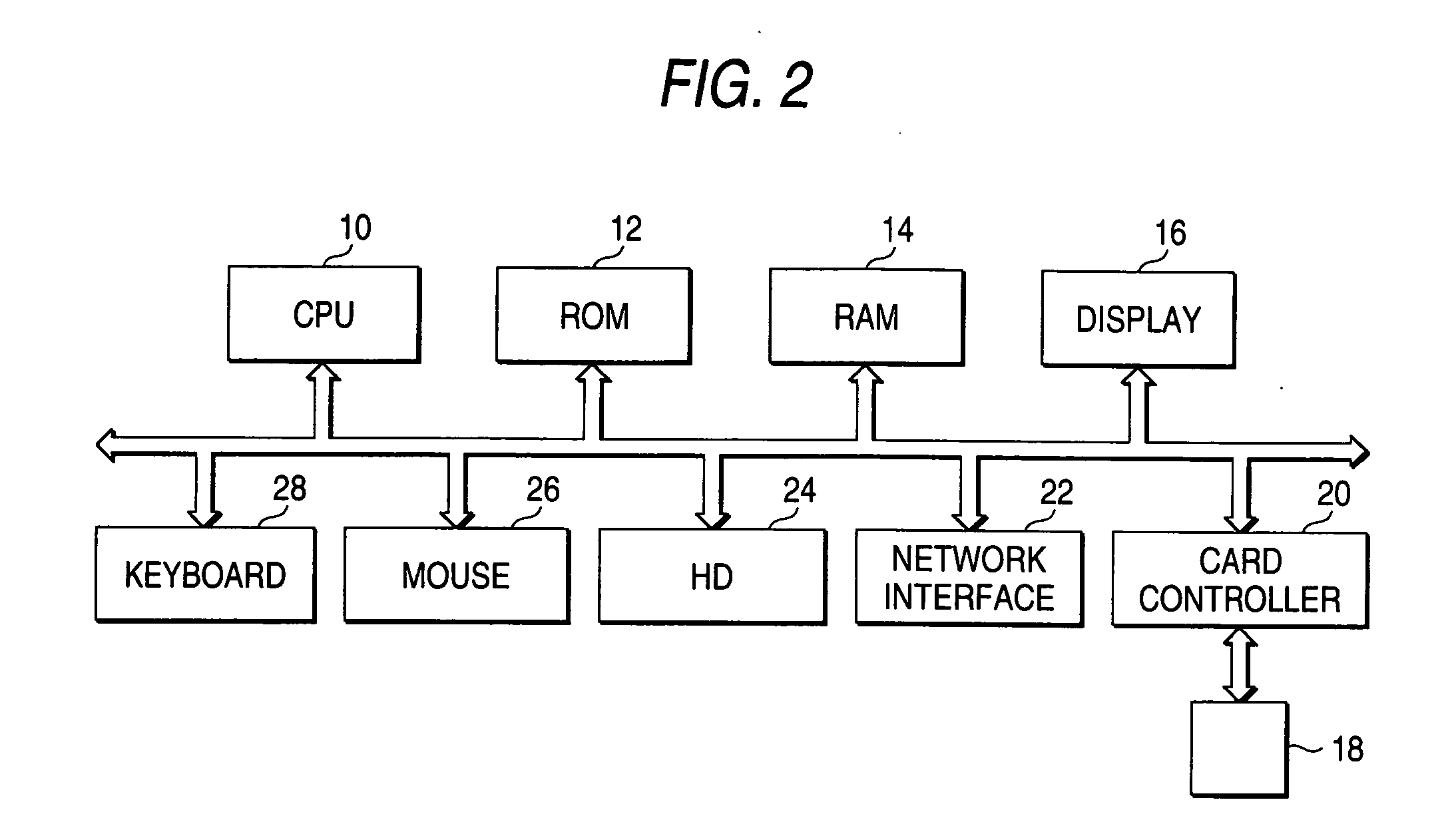
[0037]FIG. 2 is a block diagram showing an image recording apparatus according to the first embodiment of the invention. This image recording apparatus is a computer system which executes an image recording program described later to record image data in a removable memory 18. The computer system includes a CPU 10, a ROM 12, a RAM 14, a display 16, a keyboard 28, a mouse 26, a hard disc device 24, a card controller 20, a network interface 22 etc. These respective constituent elements are coupled from one another through a bus.
[0038] The CPU 10 executes the image recording program stored in the hard disc device 24 to execute an image data processing described later thereby to control the RAM 14, the display 16, the hard disc device 24, the card controller 20 etc. through a not-shown device controller. The ROM 12 is a non-volatile memory in which a control program and data necessary at the minimum for the CPU 10 to operate is stored in advance. The RAM 14 is a memory in which various...
second embodiment
[0051] The second embodiment of the invention differs from the first embodiment in the processing of the first and second pseudo channels but is common to the first embodiment in other points.
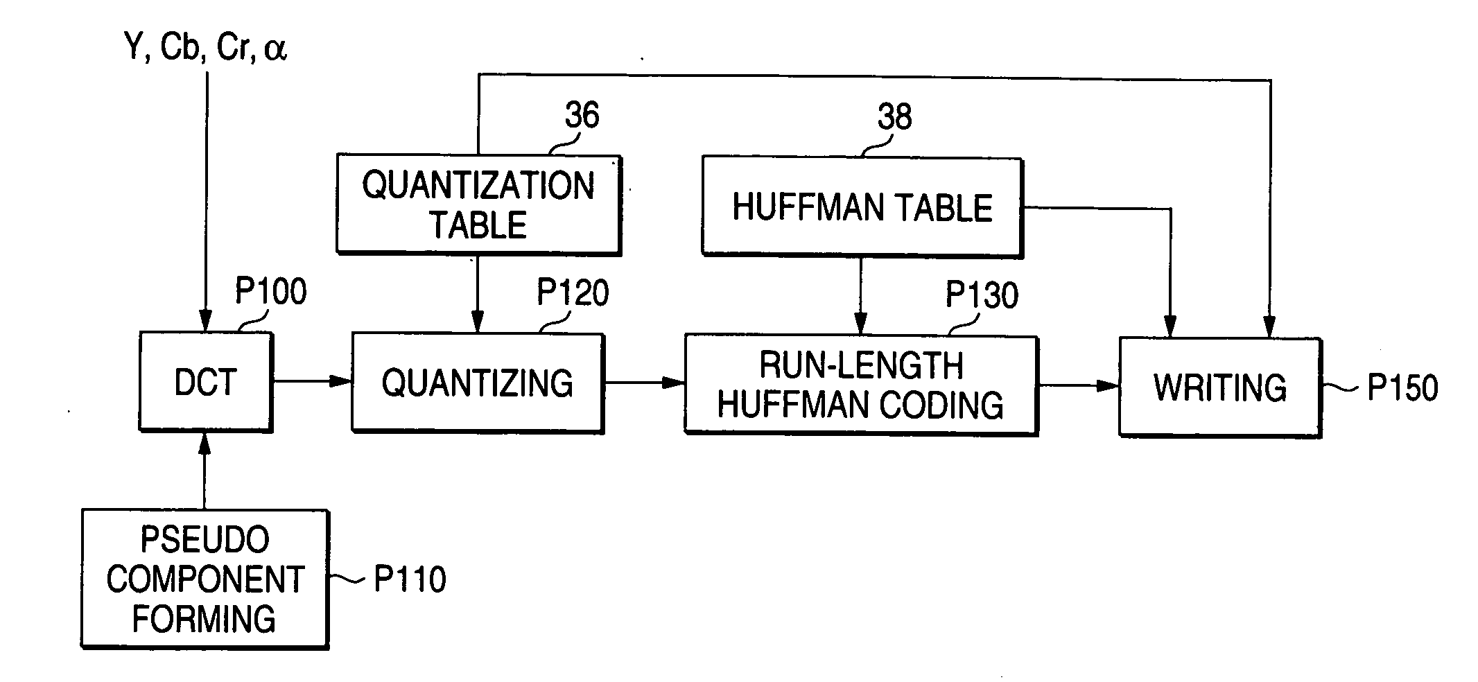
[0052]FIG. 8 is a block diagram showing respective means for implementing the image recording processing in the image recording apparatus. A DCT process P105 implements discrete cosine transformation (DCT) at each block. The DCT process P105 inputs three channel image components such as Y / Cb / Cr and an alpha channel and outputs DCT coefficients thereof.
[0053] The first pseudo channel and the second pseudo channel are outputted to a quantizing process P120 from a pseudo component forming process P112. Each of the first pseudo channel and the second pseudo channel has a data structure same as that of the DCT coefficients of the alpha channel. That is, the pseudo component forming process P112 outputs two data sets each constituted by the same number of pixels and the same level number of gradien...
third embodiment
[0055] The third embodiment of the invention differs from the first embodiment in the processing of the first and second pseudo channels but is common to the first embodiment in other points.
[0056]FIG. 9 is a block diagram showing respective means for implementing the image recording processing in the image recording apparatus. A DCT process P105 is same as that of the second embodiment and so the explanation thereof is omitted.
[0057] A quantizing process P125 implements the quantization. The quantizing process P125 inputs the DCT coefficients of the three channel image components such as Y / Cb / Cr and the alpha channel and outputs quantized values thereof (quantized DCT coefficients). The representative value of the quantization is stored in a quantization table 36. The quantizing process P125 quantizes the inputted DCT coefficients in a manner that the quantizing process obtains the address of the quantization table where the quantization representative value is stored from the DC...
PUM
 Abstract
Description
Claims
Application Information
 - R&D
- Intellectual Property
- Life Sciences
- Materials
- Tech Scout
- Unparalleled Data Quality
- Higher Quality Content
- 60% Fewer Hallucinations
Browse by: Latest US Patents, China's latest patents, Technical Efficacy Thesaurus, Application Domain, Technology Topic, Popular Technical Reports.
© 2025 PatSnap. All rights reserved.Legal|Privacy policy|Modern Slavery Act Transparency Statement|Sitemap|About US| Contact US: help@patsnap.com