Plasma lamp with dielectric waveguide

a dielectric waveguide and plasma lamp technology, applied in waveguides, structural circuit elements, sustainable buildings, etc., can solve the problems of less expensive, more reliable, and longer useful life of electrodehydeless plasma lamps, and achieve the effects of reducing the overall lamp size, and reducing the cost of production

Inactive Publication Date: 2005-11-10
LUXIM CORP
View PDF90 Cites 34 Cited by
  • Summary
  • Abstract
  • Description
  • Claims
  • Application Information

AI Technical Summary

Benefits of technology

[0012] This invention provides distinct advantages over the electrodeless plasma lamps in the related art, such as brighter and spectrally more stable light, greater energy efficiency, smaller overall lamp sizes, and longer useful life spans. Rather than using a waveguide with an air-filled resonant cavity, embodiments of the invention use a waveguide having a body consisting essentially of at least one dielectric material having a dielectric constant greater than approximately 2. Such dielectric materials include solid materials such as ceramics, and liquid materials such as silicone oil. A larger dielectric constant permits “dielectric waveguides” to be significantly smaller than waveguides of the related art, enabling their use in many applications where the smallest size achievable heretofore has made such use impossible or impractical.

Problems solved by technology

Because they do not use electrodes, electrodeless plasma lamps often have longer useful lifetimes than other lamps.
However, for many applications, light sources that are brighter, smaller, less expensive, more reliable, and have long useful lifetimes are desired, but such light sources until now have been unavailable.
Although there is tolerance in the frequencies that may be used to power the lamps, in practice, the power sources are limited to microwave frequencies in the range of 1-10 GHz.
However, for many applications, such as for high-resolution monitors, bright lamps, and projection TVs, these sizes remain prohibitively large.
Quartz bulbs, however, are prone to failure because the plasma temperature can be several thousand degrees centigrade, which can bring the quartz wall temperature to near 1000° C. Furthermore, quartz bulbs are unstable in terms of mechanical stability and optical and electrical properties over long periods.
However, over half of the energy used to generate and maintain the plasma typically is lost as heat, making heat dissipation a problem.
Hot spots can form on the bulb causing spotting on the bulb and thereby reducing the efficiency of the lamp.
These solutions, however, add structure to the lamp, thereby increasing size and cost.

Method used


Image

  • Plasma lamp with dielectric waveguide
  • Plasma lamp with dielectric waveguide
  • Plasma lamp with dielectric waveguide

Examples


Embodiment Construction

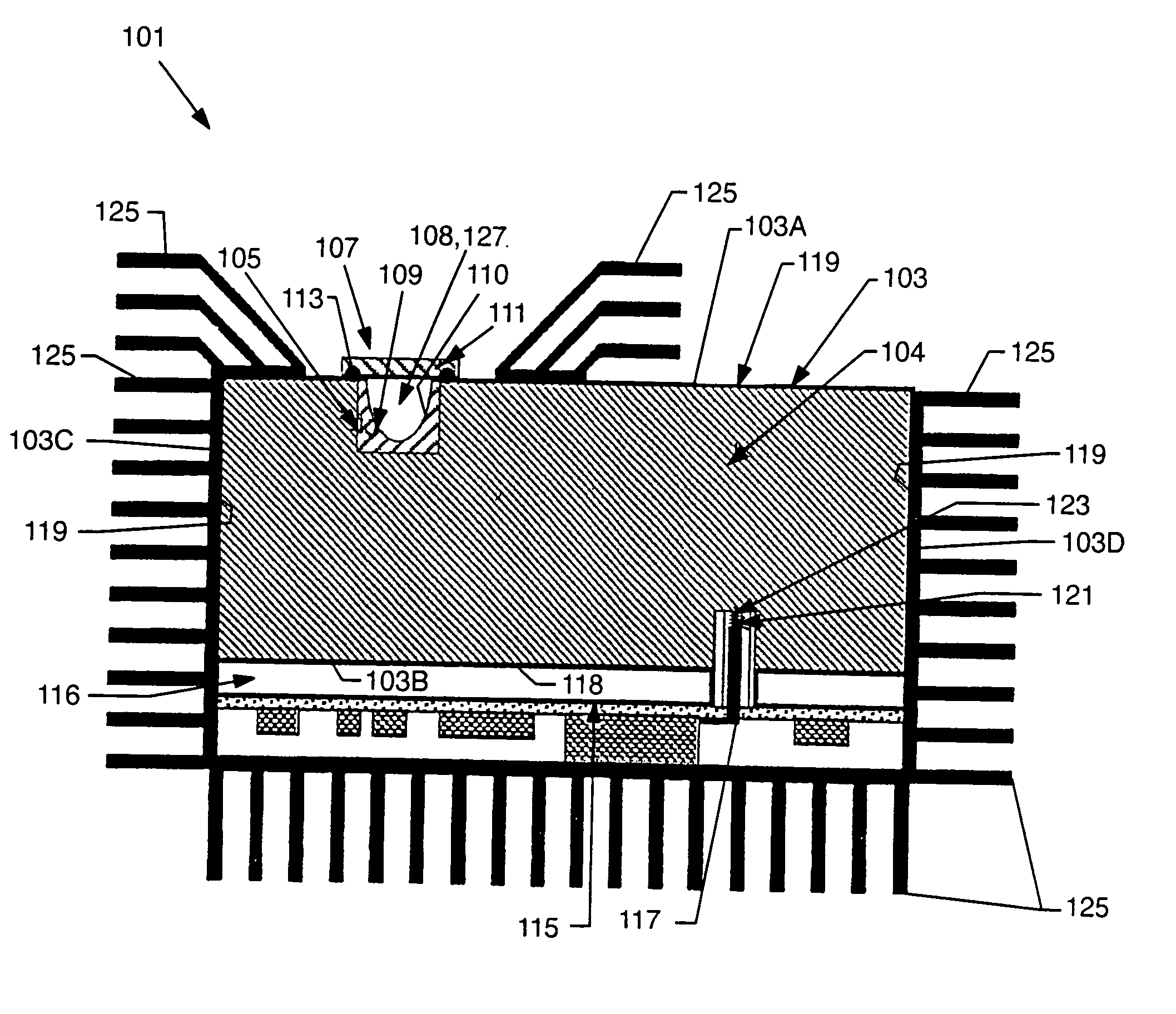
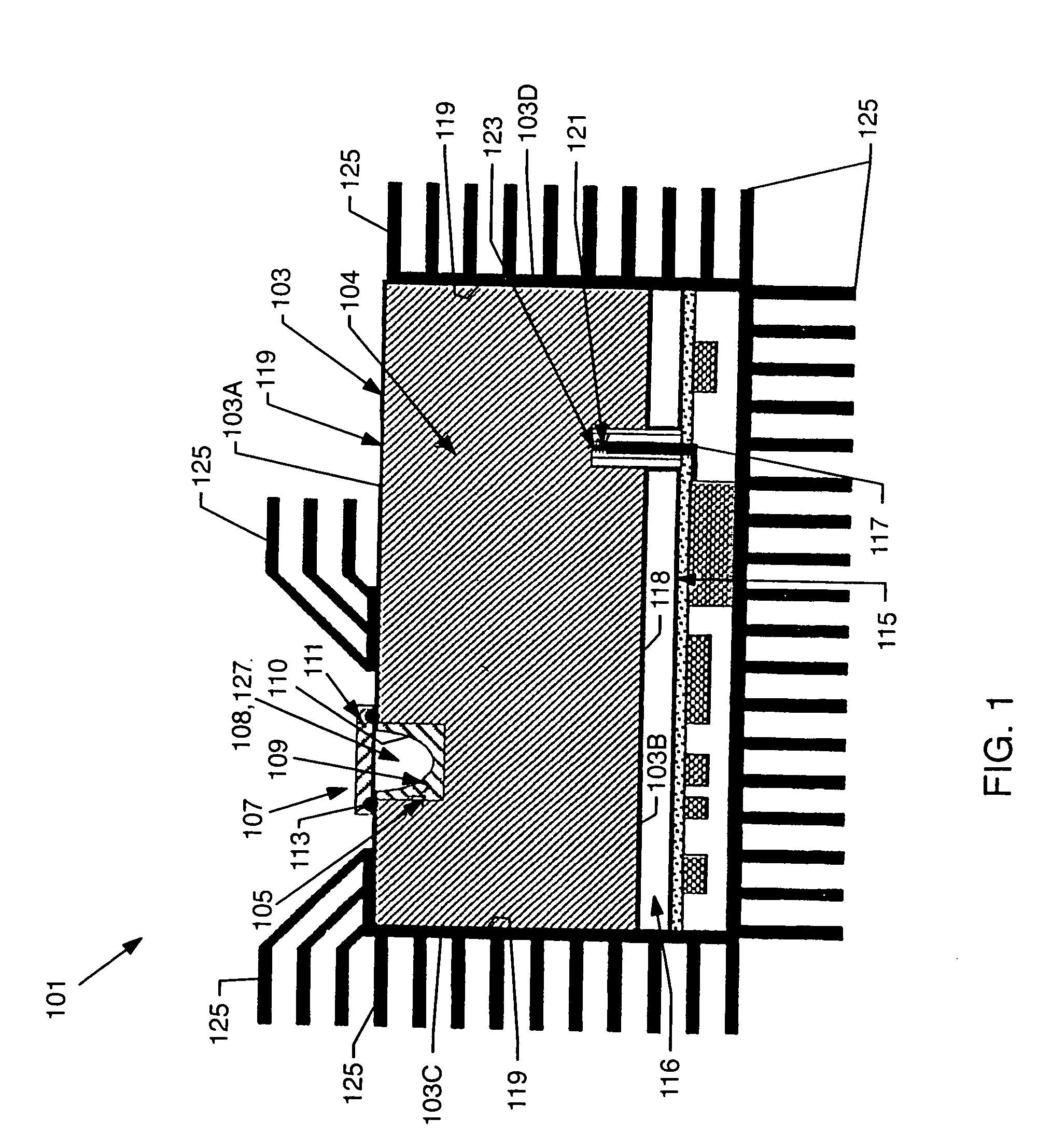
[0023] Turning now to the drawings, FIG. 1 illustrates a preferred embodiment of a dielectric waveguide integrated plasma lamp (DWIPL) 101. DWIPL 101 includes a source 115 of microwave radiation, a waveguide 103 having a body 104 formed of a solid dielectric material, and a microwave probe 117 coupling the radiation source 115 to the waveguide 103. Waveguide103 is determined by opposed sides 103A, 103B, and opposed sides 103C, 103D generally transverse to sides 103A, 103B. As used herein, the term “waveguide” generally refers to any device having a characteristic and purpose of at least partially confining electromagnetic energy. As used herein, the term “dielectric waveguide” refers to a waveguide having a body consisting essentially of at least one dielectric material having a dielectric constant greater than approximately 2. As used herein, the term “probe” is synonymous with “feed” in the '718 application. DWIPL 101 further includes a bulb 107, disposed proximate to side 103A an...


PUM


Abstract

A dielectric waveguide integrated plasma lamp (DWIPL) with a body consisting essentially of at least one dielectric material having a dielectric constant greater than approximately 2, and having a shape and dimensions such that the body resonates in at least one resonant mode when microwave energy of an appropriate frequency is coupled into the body. A bulb positioned in at least one lamp chamber in the body contains a gas-fill which when receiving energy from the resonating body forms a light-emitting plasma.

Description

CROSS-REFERENCE TO RELATED APPLICATIONS [0001] This application is a continuation of U.S. application Ser. No. 09 / 809,718 (“'718”) filed on Mar. 15, 2001, entitled “Plasma Lamp With Dielectric Waveguide,” which claims priority to U.S. provisional application Ser. No. 60 / 222,028 filed on Jul. 31, 2000, entitled “Plasma Lamp.” application Ser. Nos. 09 / 809,718 and 60 / 222,028 are hereby incorporated herein by reference.BACKGROUND OF THE INVENTION [0002] 1. Field of the Invention [0003] The field of the present invention relates to devices and methods for generating light, and more particularly to electrodeless plasma lamps. [0004] 2. Related Art [0005] Electrodeless plasma lamps provide point-like, bright, white light sources. Because they do not use electrodes, electrodeless plasma lamps often have longer useful lifetimes than other lamps. Electrodeless plasma lamps in the related art have certain common features. For example in U.S. Pat. No. 4,954,755 to Lynch et al., U.S. Pat. No. 4,...

Claims


Application Information

Patent Timeline
Patent Type & Authority Applications(United States)
IPC IPC(8): H01J61/12H01J61/30H05B41/24H01J61/52H01J65/04H01P3/16
CPCH01J7/46H01J61/12H01J61/30Y02B20/22H01J65/044H01P3/16H01J61/52Y02B20/00H01J65/04
Inventor ESPIAU, FREDERICK M.JOSHI, CHANDRASHEKHAR J.CHANG, YIAN
Owner LUXIM CORP
Why Eureka
Try Eureka