
Encapsulating OLED devices

a technology of oled devices and encapsulation, which is applied in the direction of discharge tubes/lamp details, discharge tubes luminescnet screens, electric discharge lamps, etc., can solve the problems of unprotected devices being prone to rapid degradation of performance, and unprotected devices being subject to mechanical damage, etc., to achieve excellent protection of electronic devices, increase the bond strength between a cover and a device, and not degrade the electrical properties of devices

Inactive Publication Date: 2005-11-10
EASTMAN KODAK CO
View PDF12 Cites 295 Cited by
  • Summary
  • Abstract
  • Description
  • Claims
  • Application Information

AI Technical Summary

Benefits of technology

The present invention provides an OLED device that is protected against moisture, with good adhesion and no degradation of electrical properties. The sealing step is also more robust. The invention can be used in a top-emitting OLED, allowing for higher aperture ratios and more complex circuitry on the substrate.

Problems solved by technology

Further, top-emitting active matrix OLED devices can have much more complex circuitry because the light does not need to be emitted through the thin film transistors (TFTs), capacitors, wiring lines, etc.
Despite their advantages, unprotected OLED display devices are prone to rapid degradation of performance due to adverse effects of oxygen and / or moisture present in the ambient environment.
Additionally, unprotected devices can be subject to mechanical damage caused by abrasion.
Various efforts have been directed at providing packaged OLED displays in which the packaging approaches offer improved operational lifetime of displays, which is still limited so that widespread adoption of OLED display devices is currently restricted.
However, it is very difficult to completely seal an OLED using a protective film alone.
So-called “dark spots” are a common problem, and are often attributable to the presence of dust particles.
Unfortunately, most thin film coating methods do not completely seal the dust particles, and a path for moisture penetration can still occur.
However, desiccant can be expensive.
This can result in further increases in manufacturing costs.
If desiccant is limited only to areas where there is no light emission, there can be insufficient area to ensure adequate moisture protection, thus reducing the life of the display.
This provides a problem because it may reduce efficiency and increase display size.
Although this can result in a seal having very low water permeability, it has been found that the laser can damage the electrode lines.
This damage results in greatly reduced conductivity in the glass seal area and much higher driving voltages or even device failure.

Method used


Image

  • Encapsulating OLED devices
  • Encapsulating OLED devices
  • Encapsulating OLED devices

Examples


examples

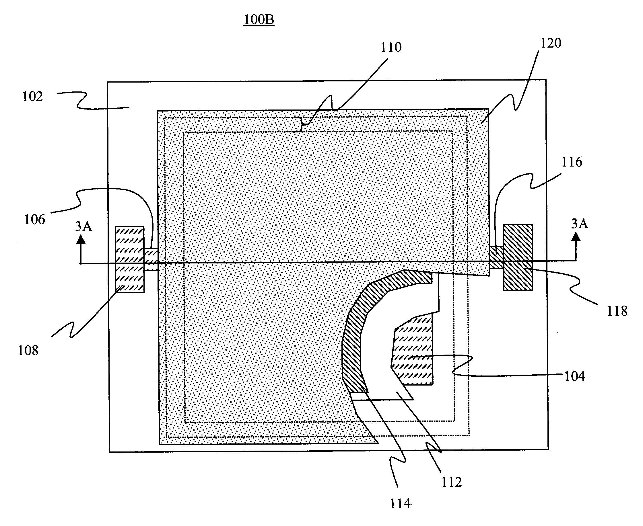
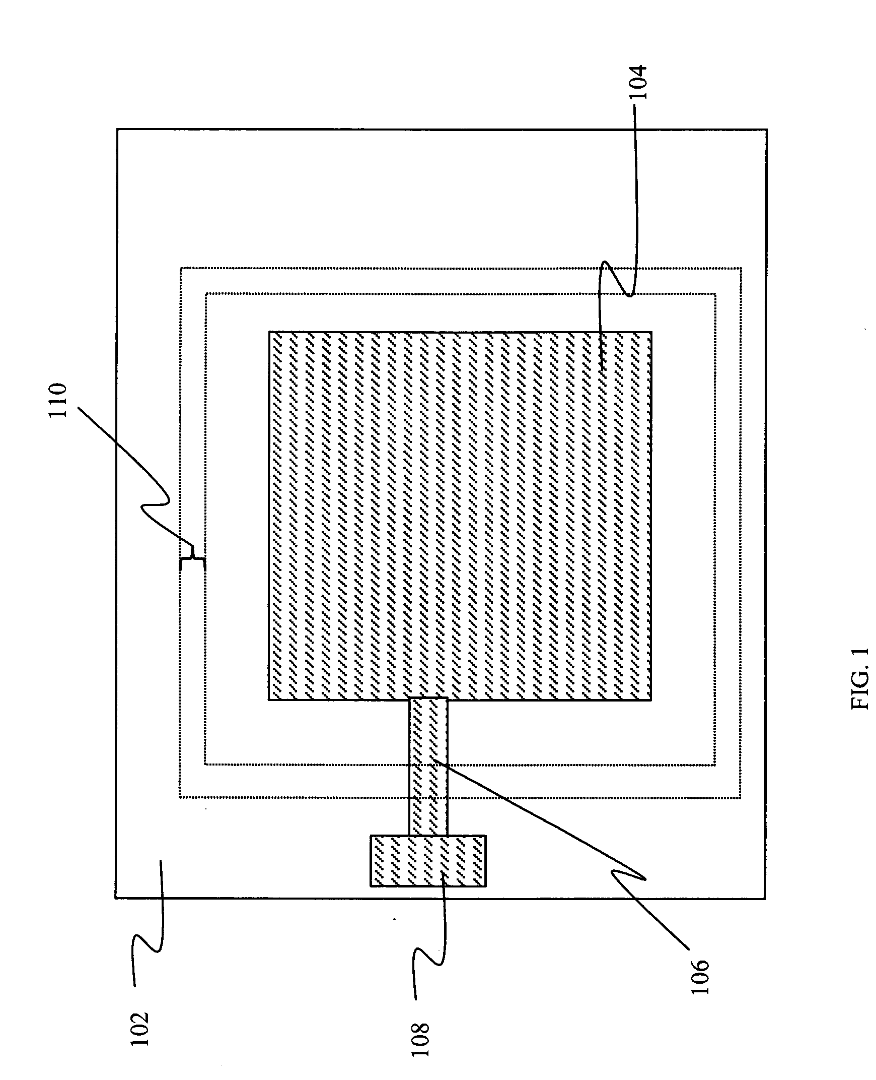
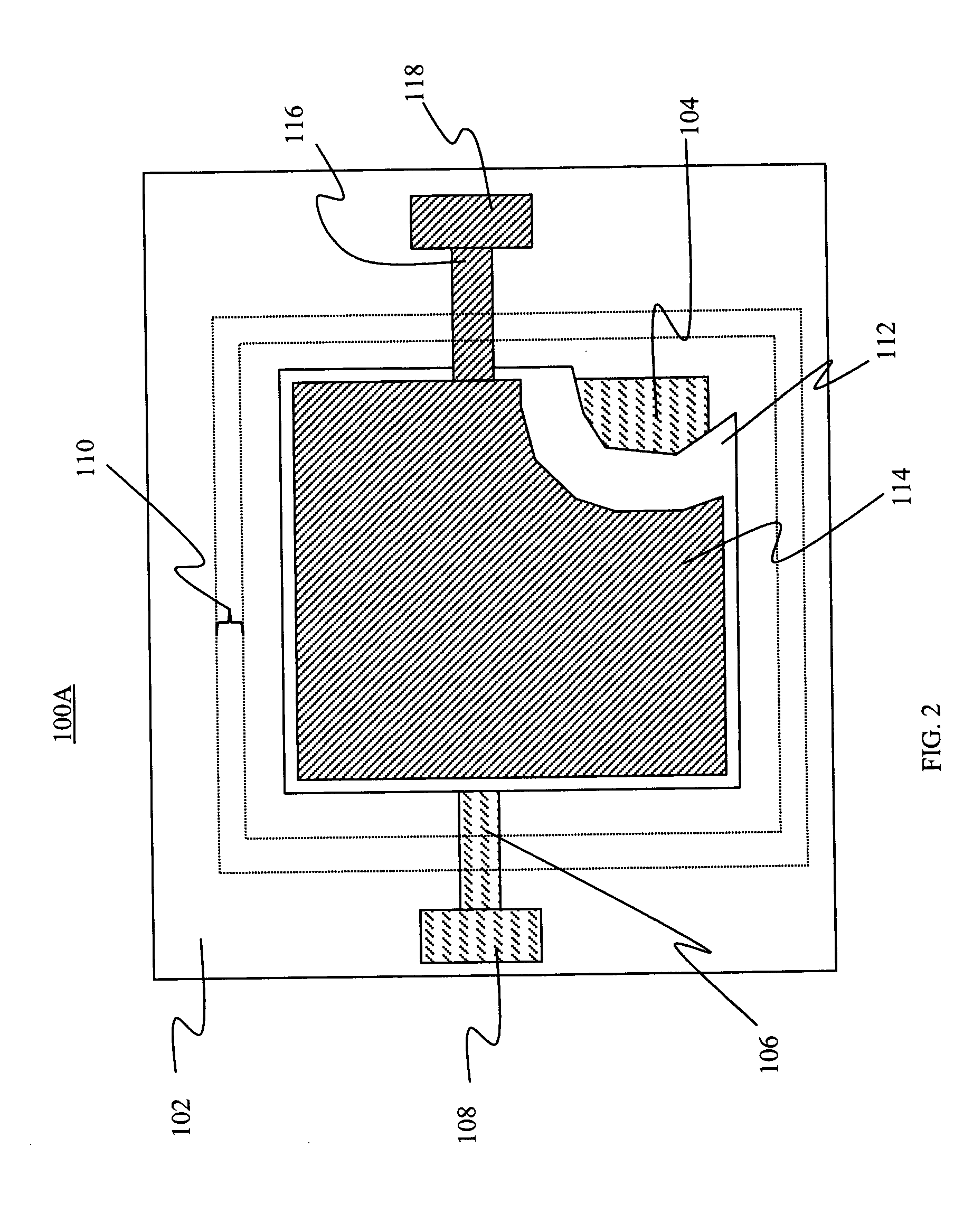
[0150] In order to demonstrate the effectiveness of the embodiments and methods of this invention, OLED devices were encapsulated in a manner described herein and were subjected to tests that are customary to display evaluation. Examples of possible assessment criteria include changes in electrical resistance of the display interconnect lines, changes in seal bond strength and moisture permeation into the encapsulate device under certain prolonged environmental conditions. One method to evaluate the level of moisture permeation is to observe the formation of dark spots in the display area. An alternative method to evaluate levels of moisture permeation is to observe the change in optical density of a Ca coating that is deposited onto a portion of the inside surface of a glass cover by means of vapor deposition. If moisture is present inside the space enclosed by the encapsulation, it reacts with the Ca coating forming CaO and reducing the optical density of the patch.

[0151] Measure...


PUM


Abstract

An encapsulated OLED device includes a substrate having a predetermined glass seal area and defining a sealed region and one or more OLED unit(s) provided over the substrate, each OLED unit having a light-emitting portion including at least one first electrode, at least one second electrode spaced from the first electrode, and an organic EL media layer provided between the first and second electrodes, wherein the light-emitting portion is provided within the sealed region. The device also includes an inorganic protection layer provided over the glass seal area and over at least a portion of the sealed region, a cover provided over the substrate and OLED unit(s), and sintered glass frit seal material provided in the glass seal area and in contact with both the cover and the inorganic protection layer to bond the cover to the inorganic protection layer and provide sealing against moisture penetration into the sealed region.

Description

CROSS REFERENCE TO RELATED APPLICATIONS [0001] Reference is made to commonly assigned U.S. patent application Ser. No. 10 / 807,486 filed Mar. 23, 2004 by Fridrich Vazan et al., entitled “Encapsulating OLED Devices,” the disclosure of which is herein incorporated by reference.FIELD OF THE INVENTION [0002] The present invention relates to protecting OLED devices from ambient moisture. BACKGROUND OF THE INVENTION [0003] Organic light-emitting diode (OLED) devices, also referred to as organic electroluminescent (EL) devices or OLEDs, have numerous well known advantages over other flat-panel display devices currently in the market place. Among these advantages are brightness of light emission, relatively wide viewing angle, reduced electrical power consumption compared to, for example, liquid crystal displays (LCDs) using backlighting, and a wider spectrum of colors of emitted light in full-color OLED displays. [0004] Applications of OLED devices include active matrix image displays, pass...

Claims


Application Information

Patent Timeline
Patent Type & Authority Applications(United States)
IPC IPC(8): H05B33/00H05B33/04H10K99/00
CPCH01L27/3297H01L51/5262H01L51/5237H10K59/179H10K59/131H10K59/873H10K59/874H10K59/871H10K50/846H10K50/841H10K50/844H10K50/85
Inventor GHOSH, AMALKUMAR P.BOROSON, MICHAEL L.VAZAN, FRIDRICHYOKAJTY, JOSEPH E.OLIN, GEORGE R.
Owner EASTMAN KODAK CO
Learn More