
Implantable analyte sensor

an analyte sensor and sensor technology, applied in the field of analyte sensors, can solve the problems of inability to make educated insulin therapy decisions, lack of continuous care (short-term sensors), and likely diabetes, and achieve the effect of accurate and reliable function and improved patient convenience and car

Inactive Publication Date: 2005-11-03
DEXCOM
View PDF99 Cites 1266 Cited by
  • Summary
  • Abstract
  • Description
  • Claims
  • Application Information

AI Technical Summary

Benefits of technology

[0005] There is a need for a device a long-term, implantable analyte sensor that functions accurately and reliably, to provide improved patient convenience and care.
[0019] In a fifth embodiment, a method for implantation of an analyte sensor in a host is provided, the method including: forming a precisely dimensioned pocket in the subcutaneous space of the host, wherein the pocket is dimensioned no greater than the dimensions of the analyte sensor; inserting the analyte sensor into the precisely-dimensioned pocket so as to minimize movement of the sensor within the pocket.
[0020] In an aspect of the fifth embodiment, the step of forming a pocket includes using a tool that allows precise dimensioning of the pocket. In an aspect of the fifth embodiment, the tool includes a head dimensioned substantially similar to the dimensions of the analyte sensor and a handle for guiding the head into the pocket. In an aspect of the fifth embodiment, the tool includes a head dimensioned smaller than the dimensions of the analyte sensor and a handle for guiding the head into the pocket.
[0042] In an aspect of the eleventh embodiment, the multilayer membrane further includes an interference layer that substantially prevents passage of potentially electrochemically interfering substances.
[0049] In a thirteenth embodiment, a method for casting a membrane for use with an electrochemical glucose sensor is provided, wherein the membrane substantially prevents passage of potentially electrochemically interfering substances, the method including: forming a sufficiently diluted solvent solution including a polymer and a solvent, wherein sufficiently diluted solvent solution includes a ratio of polymer to solvent of about 1 to 10 wt.% polymer to about 90 to 99 wt.% solvent; and applying the solvent solution at a sufficiently fast casting speed that substantially avoids film thickness inhomogeneities due to evaporation during casting of the sufficiently diluted solvent solution.

Problems solved by technology

In the diabetic state, the victim suffers from high blood sugar, which may cause an array of physiological derangements (for example, kidney failure, skin ulcers, or bleeding into the vitreous of the eye) associated with the deterioration of small blood vessels.
Conventionally, a diabetic person carries a self-monitoring blood glucose (SMBG) monitor, which typically comprises uncomfortable finger pricking methods.
Unfortunately, these time intervals are so far spread apart that the diabetic will likely find out too late, sometimes incurring dangerous side effects, of a hyper- or hypo-glycemic condition.
In fact, it is not only unlikely that a diabetic will take a timely SMBG value, but the diabetic will not know if their blood glucose value is going up (higher) or down (lower) based on conventional methods, inhibiting their ability to make educated insulin therapy decisions.
Unfortunately, each of these sensors suffers from various disadvantages, such as lack of continuous care (short-term sensors), discomfort (transcutaneous and partially implantable sensors), and inconvenience (sensors with multiple components).

Method used

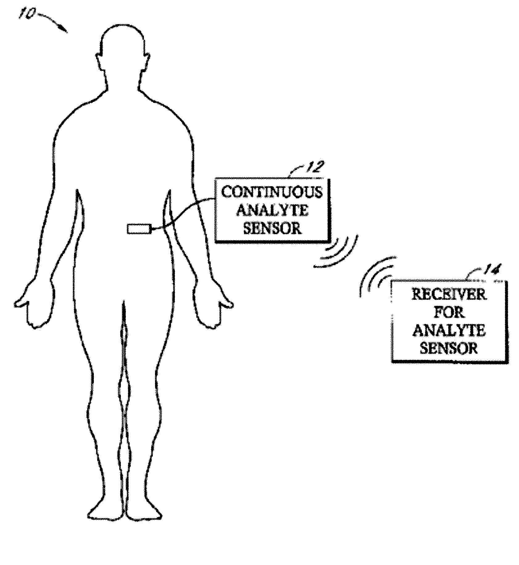
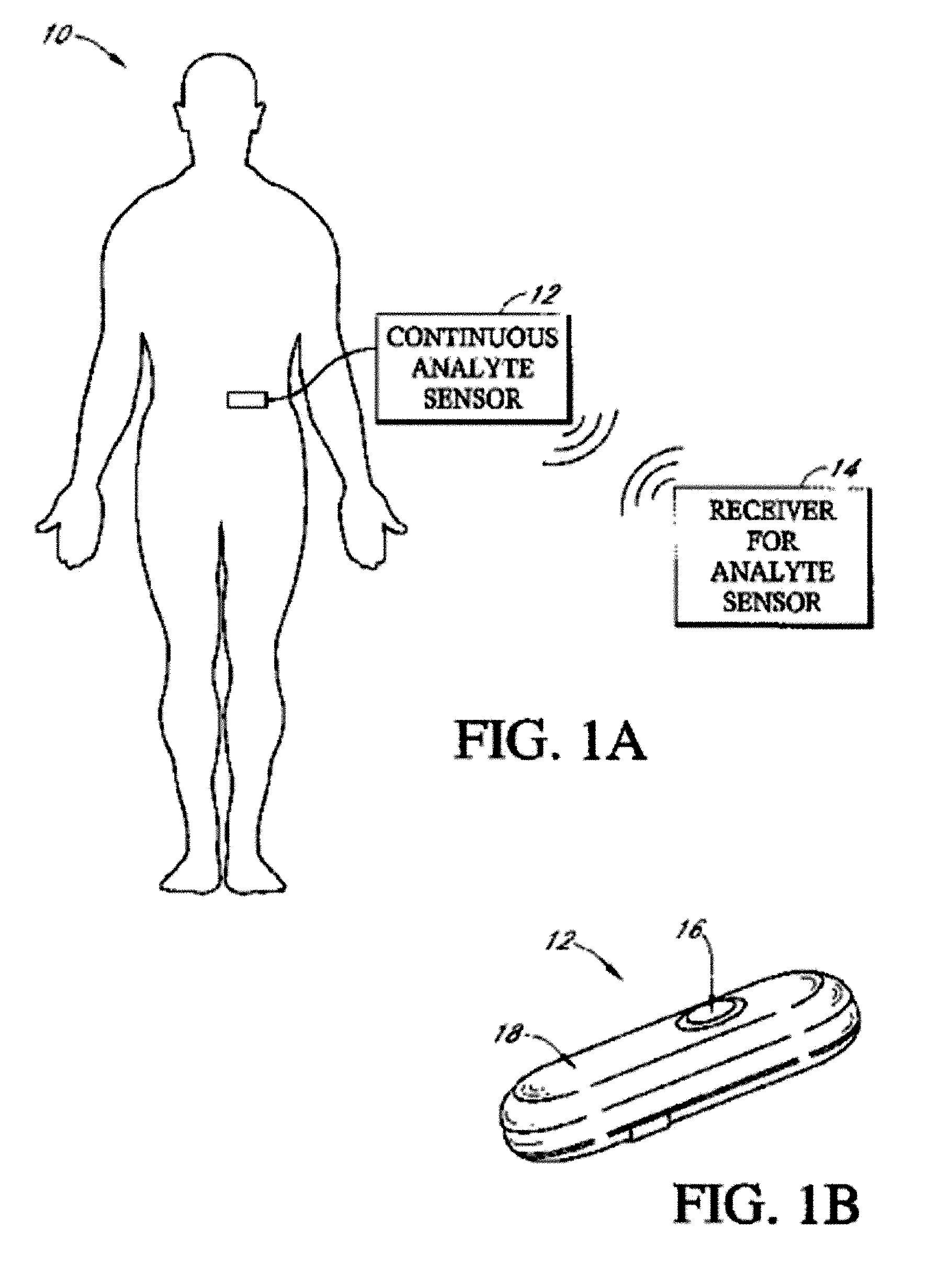

Image

  • Implantable analyte sensor
  • Implantable analyte sensor
  • Implantable analyte sensor

Examples


first embodiment

[0006] Accordingly, in a first embodiment, an implantable analyte sensor for measuring an analyte in a host is provided, the sensor including: a sensor body including a sensing region for measuring the analyte and a non-sensing region for immobilizing the sensor body in the host; a first biointerface material adjacent to the sensing region, wherein the first biointerface material includes a porous architecture that promotes vascularized tissue ingrowth and interferes with barrier cell layer formation, for allowing analyte transport to the sensing region in vivo; and a second biointerface material adjacent to at least a portion of the non-sensing region, wherein the second biointerface material includes a porous architecture that promotes tissue ingrowth for anchoring the sensor in vivo.

[0007] In an aspect of the first embodiment, the first biointerface material further includes a domain proximal to the sensing region that is impermeable to cells or cell processes and is permeable to...

second embodiment

[0010] In a second embodiment, an analyte sensor for short-term and long-term immobilization in a host’s soft tissue is provided, the sensor including: a short-term anchoring mechanism for providing immobilization of the sensor in the soft tissue prior to substantial formation of the foreign body capsule; and a long-term anchoring mechanism for providing immobilization of the sensor in the soft tissue during and after substantial formation of the foreign body capsule.

[0011] In an aspect of the second embodiment, the short-term anchoring mechanism includes a suture tab on the sensor body. In an aspect of the second embodiment, the short-term anchoring mechanism includes a suture. In an aspect of the second embodiment, the short-term anchoring mechanism includes at least one of prongs, spines, barbs, wings, and hooks. In an aspect of the second embodiment, the short-term anchoring mechanism includes a geometric configuration of the sensor body. In an aspect of the second embodimen...

third embodiment

[0013] In a third embodiment, a method for immobilizing an analyte sensor in soft tissue is provided, the method including: implanting the analyte sensor in a host; anchoring the sensor in the host prior to formation of a foreign body capsule for at least short-term immobilization of the sensor within the soft tissue of the host; and anchoring the sensor within the foreign body capsule for long-term immobilization of the sensor within the soft tissue of the host.

[0014] In an aspect of the third embodiment, the short-term immobilization step includes suturing the sensor to the host’s tissue. In an aspect of the third embodiment, the suturing step includes suturing the sensor such that the sensor is in compression. In an aspect of the third embodiment, the short term immobilization step includes utilizing at least one of prongs, spines, barbs, wings, and hooks on the sensor to anchor the sensor into the host’s tissue upon implantation.

[0015] In an aspect of the third embodiment, the...


PUM


Abstract

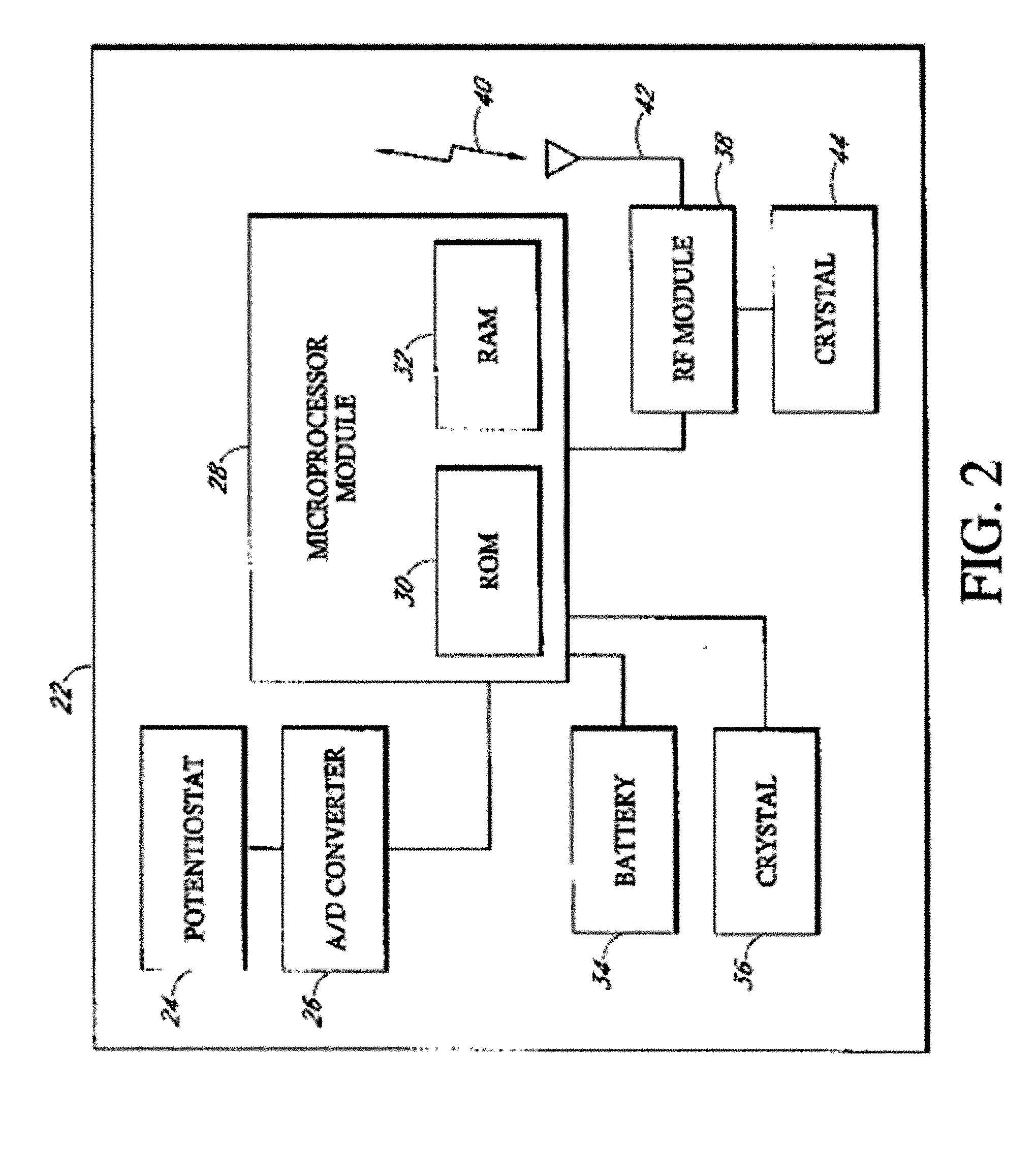
Abstract of the DisclosureAn implantable analyte sensor including a sensing region for measuring the analyte and a non-sensing region for immobilizing the sensor body in the host. The sensor is implanted in a precisely dimensioned pocket to stabilize the analyte sensor in vivo and enable measurement of the concentration of the analyte in the host before and after formation of a foreign body capsule around the sensor. The sensor further provides a transmitter for RF transmission through the sensor body, electronic circuitry, and a power source optimized for long-term use in the miniaturized sensor body.

Description

Detailed Description of the InventionField of the Invention[0001] The present invention relates generally to systems and methods for making and using an implantable analyte sensor.Background of the Invention[0002] Diabetes mellitus is a disorder in which the pancreas cannot create sufficient insulin (Type I or insulin dependent) and / or in which insulin is not effective (Type 2 or non–insulin dependent). In the diabetic state, the victim suffers from high blood sugar, which may cause an array of physiological derangements (for example, kidney failure, skin ulcers, or bleeding into the vitreous of the eye) associated with the deterioration of small blood vessels. A hypoglycemic reaction (low blood sugar) may be induced by an inadvertent overdose of insulin, or after a normal dose of insulin or glucose-lowering agent accompanied by extraordinary exercise or insufficient food intake.[0003] Conventionally, a diabetic person carries a self-monitoring blood glucose (SMBG) monitor, which ...

Claims


Application Information

Patent Timeline
IPC IPC(8): A61B5/00A61B5/05
CPCA61B5/0031A61B5/6882A61B5/14865A61B5/14532
Inventor BRAUKER, JAMES H.TAPSAK, MARK A.SHULTS, MARKCARR-BRENDEL, VICTORIAFISHER, JACK C.SEARE, WILLIAM J. JR.NEALE, PAUL V.
Owner DEXCOM
Learn More