
Passive entry systems for vehicles and other applications

a technology for vehicles and other applications, applied in the field of wireless command systems, can solve the problems of patent failure to disclose the general use of keys, the failure of patent disclosure of vehicle mounted keypads, and the use of keys operable, so as to prevent false activation, increase power consumption, and preserve battery power.

Inactive Publication Date: 2005-11-03
PEARSON DAVID +2
View PDF20 Cites 126 Cited by
  • Summary
  • Abstract
  • Description
  • Claims
  • Application Information

AI Technical Summary

Benefits of technology

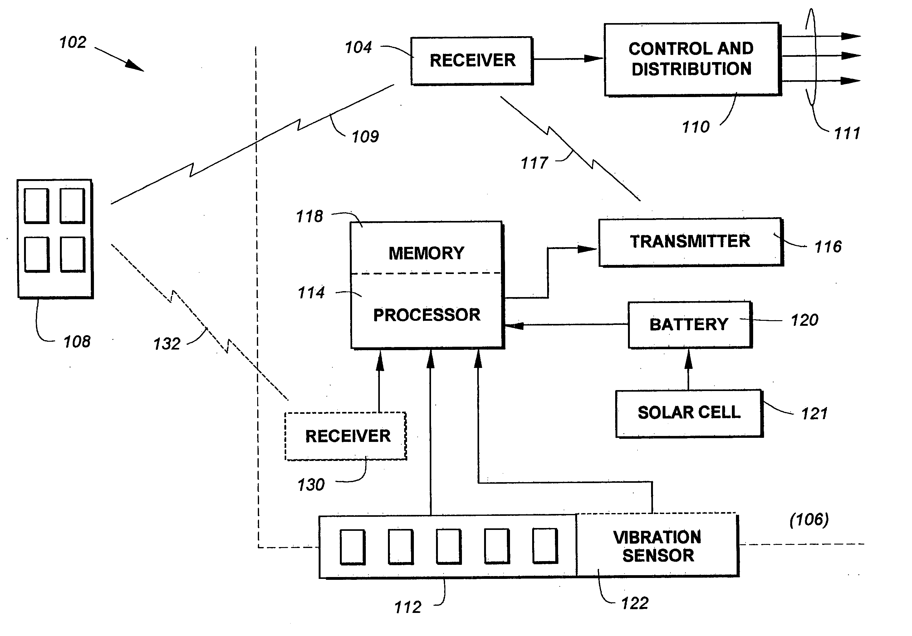
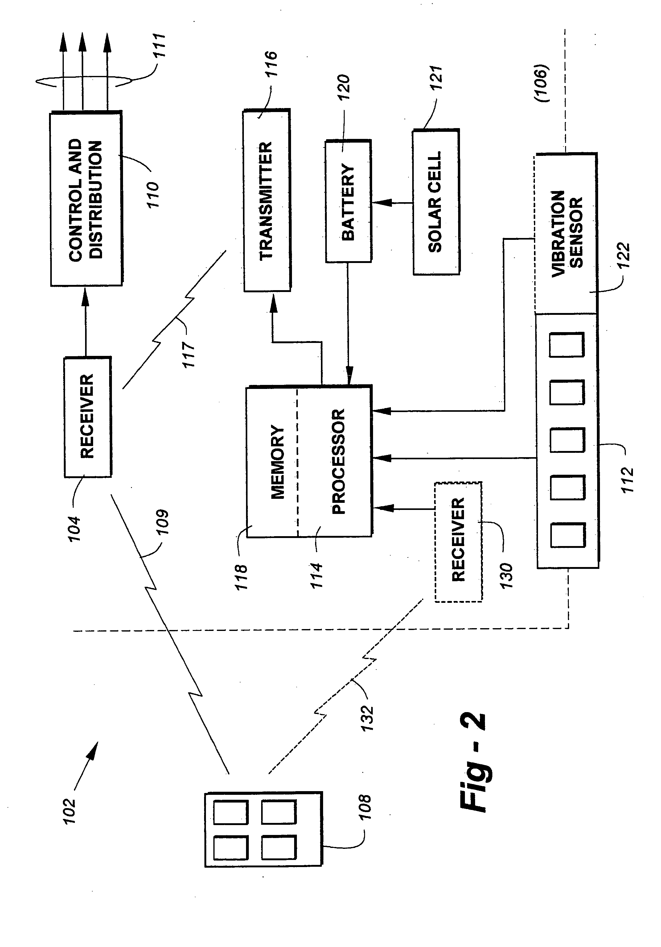
[0012] The inventive transmitter is preferably battery-operated, thereby obviating the need for extraneous wiring to the device. To conserve battery power, the system automatically powers down during periods of non-use, with the entry of an appropriate stimulus being used to initiate operational modes requiring increased power consumption. Appropriate authorization may be used as a wake-up signal such that for a short period of time—a few seconds, for example—before initiating a desired function. In another embodiment, a sensor is used to detect a person's voice, other sound, or a vibration such as tapping on the glass of the vehicle which, in turn, functions as a wake-up signal. To further prevent false activation, the tapping or other input associated with the wake-up may, itself, be programmably encoded.

Problems solved by technology

Though convenient, keyless entry systems of the type just described may cost several hundred dollars, even if factory installed.
This patent fails to disclose a vehicle mounted keypad in general, or the use of keys operable through glass, in particular.
This patent fails to disclose a vehicle mounted transmitter or any details of the code input portion.

Method used


Image

  • Passive entry systems for vehicles and other applications
  • Passive entry systems for vehicles and other applications
  • Passive entry systems for vehicles and other applications

Examples


Embodiment Construction

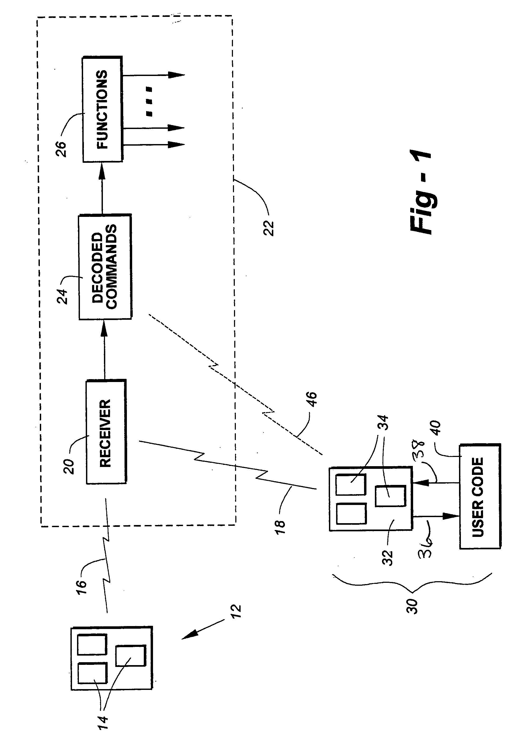
[0022]FIG. 1 is a block-diagram drawing used to introduce apparatus relevant to the invention, and to explain important functions made possible by the apparatus. The invention is configured for use in conjunction with a receiver 20 of wireless command signals 16 which may emanate from a portable control device 12 having one or more buttons 14. The receiver 20 is typically associated with the entry or operation of a system such as a vehicle 22, though it will be appreciated by one of skill in the art that the invention is equally applicable to other situations and environments such as home security, garage-door control and so forth.

[0023] Particularly in vehicular applications, the controller 12 may take the form of a hand-held “fob,” having button such as LOCK, UNLOCK, PANIC, and so forth, though as explained in further detail elsewhere herein, the invention is not limited in terms of the number or types of commands output by the device 12, or recognizable by the receiver 20. These...


PUM


Abstract

For use in conjunction with an existing wireless transmitter / receiver, a transmitter provided by the invention preferably uses some or all of the same codes as the existing remote transmitter to perform a desired function such as door or trunk unlocking, windows, light activation, and so forth. One embodiment of the invention includes a passive entry system so that only an authorized operator can use the device. In a preferred embodiment, a user carries a wallet-sized card or other device, such that upon activation of the keypad associated with the inventive transmitter, a signal is first sent to the user for verification. If the card or other device carried by the user properly transponds an appropriate authorization signal, the inventive transmitter broadcasts the codes appropriate to the function being requested. Alternatively, biometric information such a fingerprint or voiceprint may be used.

Description

REFERENCE TO RELATED APPLICATIONS [0001] This application is a continuation-in-part of U.S. patent application Ser. No. 09 / 567,582, filed May 10, 2000, which is a continuation-in-part of U.S. patent application Ser. No. 09 / 468,629, filed Dec. 21, 1999, now U.S. Pat. No. 6,617,975, which is a continuation of U.S. patent application Ser. No. 09 / 061,403, filed Apr. 16, 1998, now U.S. Pat. No. 6,031,465. This application also claims priority to U.S. Provisional Patent Application Ser. No. 60 / 564,483, filed Apr. 22, 2004. The entire content of all of which are incorporated herein by reference.FIELD OF THE INVENTION [0002] This invention relates generally to wireless command systems and, in particular, to a transmitter that uses remote transmitter codes to unlock doors or perform other functions in response to an operator input. BACKGROUND OF THE INVENTION [0003] Many higher-end cars and trucks now come equipped with keyless entry systems. These typically take the form of a pocket-sized f...

Claims


Application Information

Patent Timeline
IPC IPC(8): G06F7/04G07C9/00
CPCG07C9/00309G07C2209/63G07C9/0069G07C9/00563
Inventor PEARSON, DAVIDLEGASSE, FRANCISBURGESS, JAMES P.
Owner PEARSON DAVID
Learn More