
Method of manufacture of heat-exchanger tube structured on both sides

Active Publication Date: 2005-11-03
WIELAND WERKE AG
View PDF1 Cites 7 Cited by
  • Summary
  • Abstract
  • Description
  • Claims
  • Application Information

AI Technical Summary

Benefits of technology

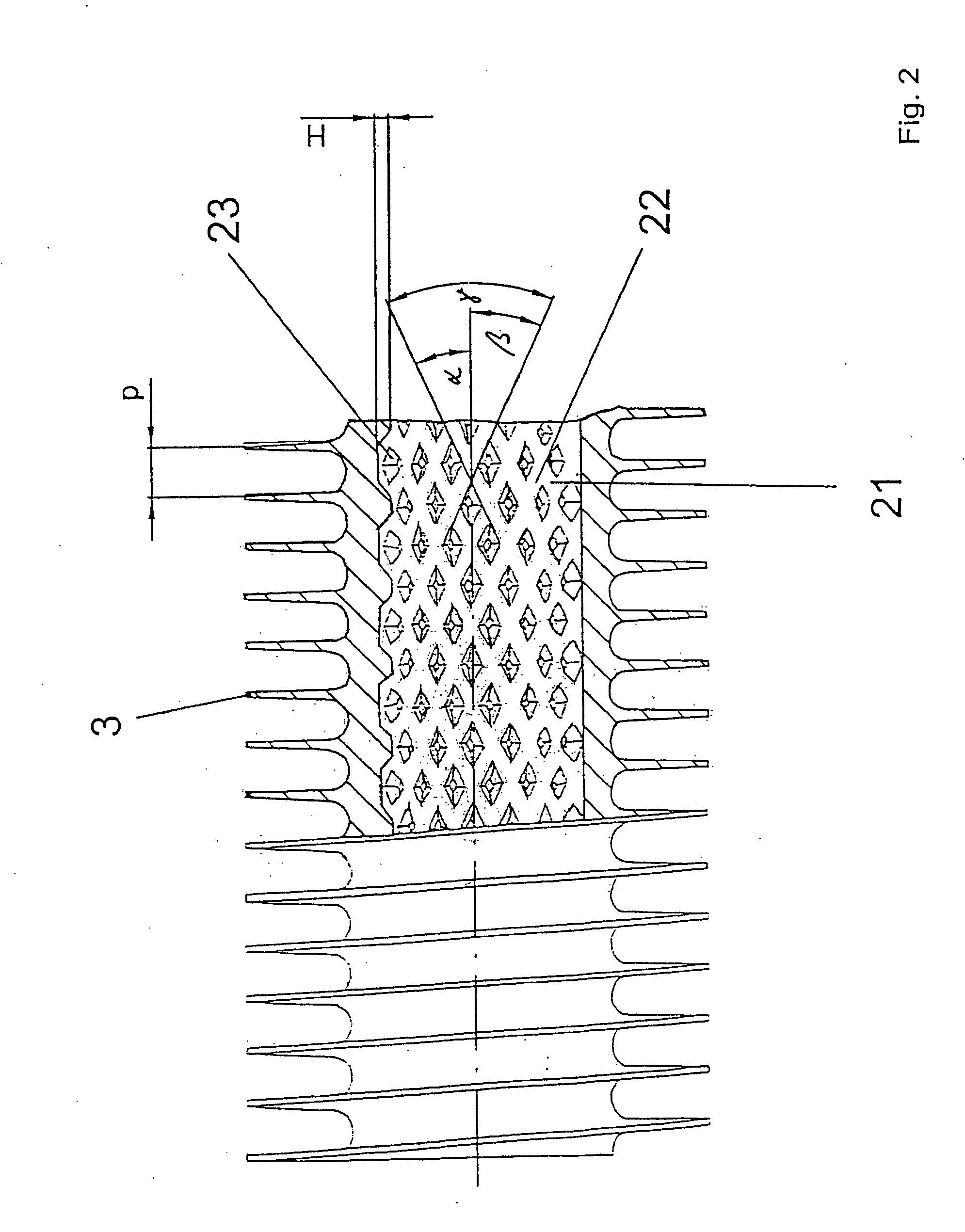
[0011] By creating the secondary grooves, the inner fins now have no longer a constant cross-section. When one follows the course of the inner fins, one sees the change in the cross-sectional form of the inner fins at the areas of the secondary grooves. Additional turbulences are created i

Problems solved by technology

This would principally be possible through an increase of the height of the inner fins which, however, is technically difficult to do because of the increasing, strong deformation of the material, and furthermore results in a heavy weight of the structured tube.
A heavy weight is, however, undesired for cost reasons.

Method used


Image

  • Method of manufacture of heat-exchanger tube structured on both sides
  • Method of manufacture of heat-exchanger tube structured on both sides
  • Method of manufacture of heat-exchanger tube structured on both sides

Examples


Embodiment Construction

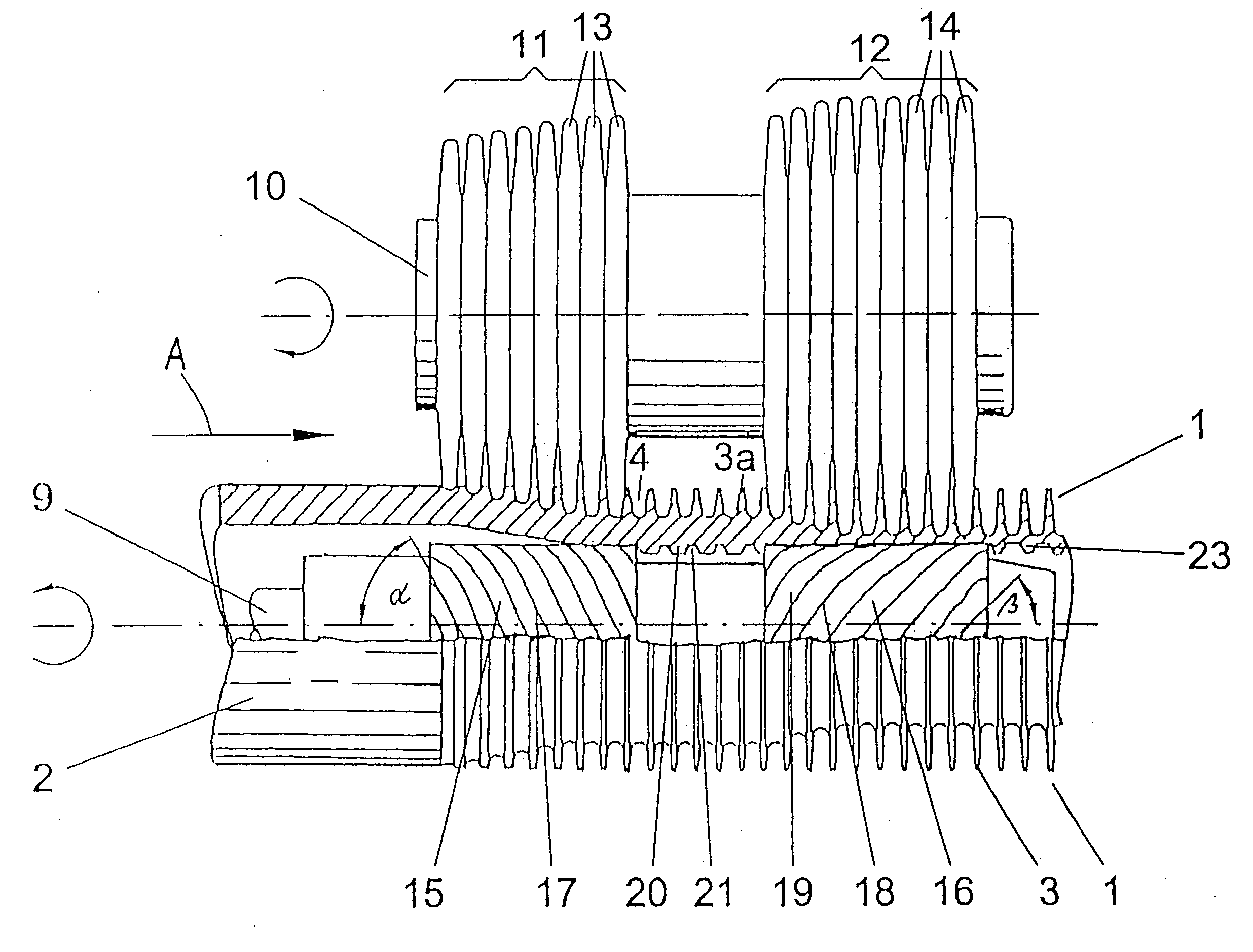
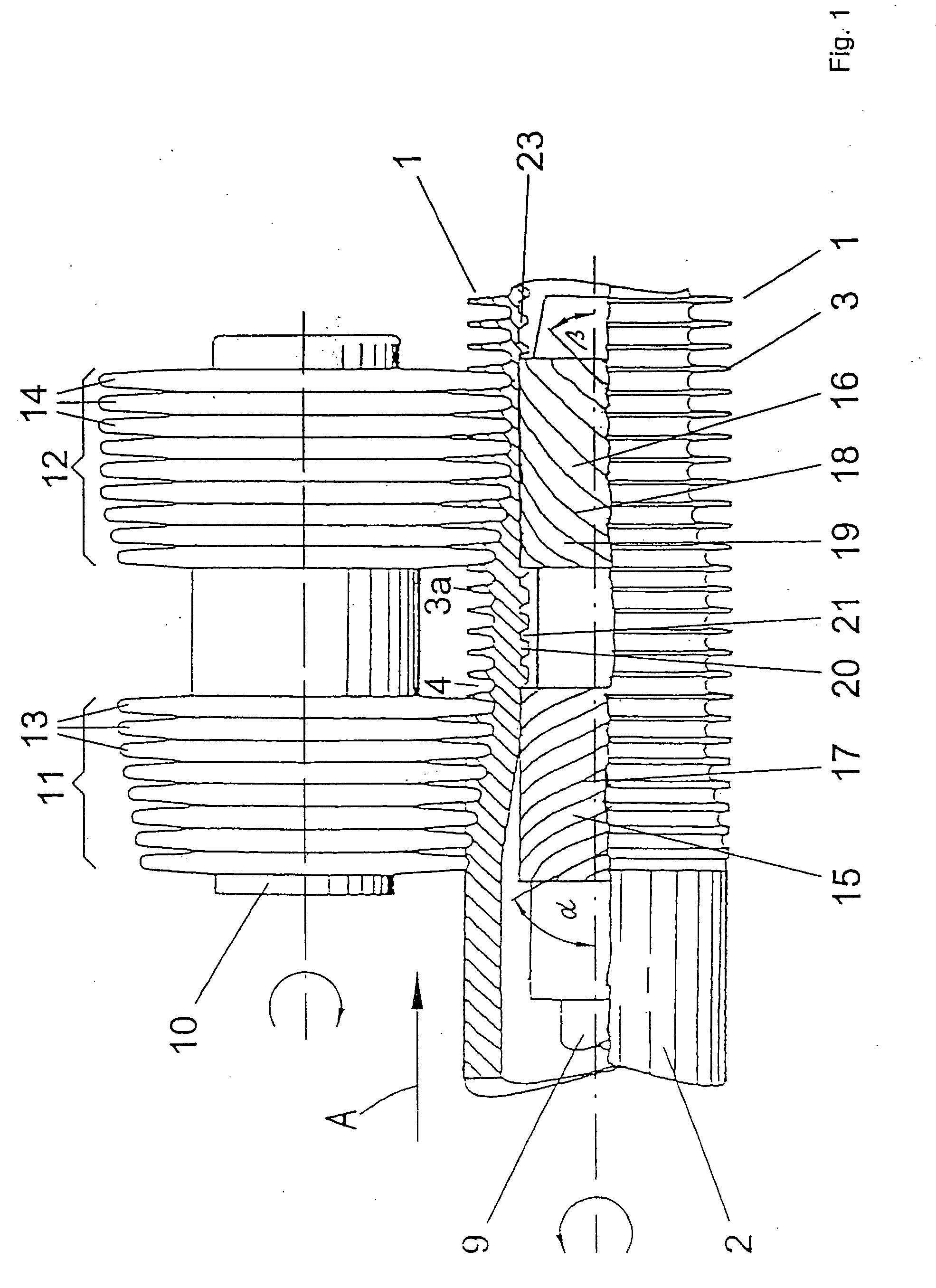
[0021] The integrally finned tube 1 according to FIGS. 1 and 2 has fins 3 helically extending over the outside of the tube. The inventive finned tube is manufactured by a finning process (compare U.S. Pat. Nos. 1,865,575 and 3,327,512; and DE 23 03 172) and by means of a device illustrated in FIG. 1.

[0022] A device is used which consists of n=3 or 4 arbors 10, onto each of which are integrated at least two rolling tools 11 and 12 which are spaced from one another. (FIG. 1 shows only one arbor for reasons of clarity.) The axis of the arbor 10 is at the same time the axis of the two associated rolling tools 11 and 12, and it extends skewed with respect to the tube axis. The arbors 10 are arranged each offset at 360° / n on the periphery of the finned tube. The arbors 10 can be fed radially. They are in turn arranged in a stationary (not illustrated) milling head. The milling head is fixed in the basic frame of the milling device. The rolling tools 11 and 12 each consist of several side...


PUM

PropertyMeasurementUnit
Angleaaaaaaaaaa
Diameteraaaaaaaaaa
Areaaaaaaaaaaa

Abstract

The invention relates to a heat-exchanger tube structured on both sides with excellent heat transfer characteristics utilizing both outer and also inner fins and secondary grooves intersecting the inner fins. Two spaced-apart rolling tools are provided in the utilized device in order to form the outer fins of two adjacent rolling tools; the inner structure is formed by two differently profiled mandrels. The first mandrel forms in a first forming area the inner fins. The second mandrel forms in a second forming area the inventive secondary grooves into the earlier created inner fins.

Description

FIELD OF THE INVENTION [0001] The invention relates to metallic heat-exchanger tubes structured on both sides, in particular finned tubes. BACKGROUND OF THE INVENTION [0002] Heat transfer occurs in many areas of the air conditioning and refrigeration engineering and in the process and energy engineering. Shell and tube heat exchangers are often utilized in these areas for heat transfer. A liquid flows hereby on the inside of the tube in many applications, which liquid is cooled off or heated depending on the direction of the heat flow. The heat is given to the medium on the outside of the tube or is removed from said medium. Tubes, which are structured on both sides, constituting the state of the art, are utilized in shell and tube heat exchangers instead of plain tubes. This intensifies the heat transfer on the inside of the tube and on the outside of the tube. The heat-flux is increased, and the heat exchanger can be built more compactly. As an alternative, it is possible to maint...

Claims


Application Information

Patent Timeline
IPC IPC(8): F28F1/36B21C37/20B21H3/04B21H3/10F28F1/42F28F13/04
CPCB21C37/207F28F1/42F28F1/422Y10T29/49382Y10T29/49385Y10T29/49378Y10T29/49391Y10T29/49377Y10T29/4935
Inventor BRAND, KARINEKNOEPFLER, ANDREASBEUTLER, ANDREASLUTZ, RONALD
Owner WIELAND WERKE AG
Learn More