
Nonlinear polarization pulse shaping mode locked fiber laser

a technology of mode-locked fiber laser and polarized polarization, which is applied in the direction of laser details, active medium shape and construction, electrical equipment, etc., can solve the problems of inability to properly and conveniently control the pulse shape of short-pulse laser, and the difficulty is even more pronounced when the pulse width is further reduced

Active Publication Date: 2005-10-27
POLARONYX
View PDF7 Cites 23 Cited by
  • Summary
  • Abstract
  • Description
  • Claims
  • Application Information

AI Technical Summary

Benefits of technology

[0007] It is therefore an object of the present invention to provide a method of using nonlinear polarization evolution (NPE) and dispersion managed fiber cavity to manipulate the pulse propagation in the cavity and balance the self phase modulati

Problems solved by technology

Conventional technologies of generating short pulse mode-locked fiber laser are still confronted with technical difficulties and limitations that the pulse shapes of the short-pulse laser cannot be properly and conveniently controlled.
The difficulty is even more pronounced when the pulse width is further reduced.
However, D. U. Noske, N. Pandit, J. R. Taylor and K. Tamura, H. A. Haus, and E. I. Ippen have showed by their experimental results that longer pulse widths and come with unwanted sidebands that degraded the performance of the soliton fiber lasers.
However, they have not achieved transform-limitedly shaped pulse, because the spectrum is not symmetrically Gaussian / Soliton shape and time bandwidth product (TBP) is too large.
It is still remained a challenge to obtain transform limited pulse.
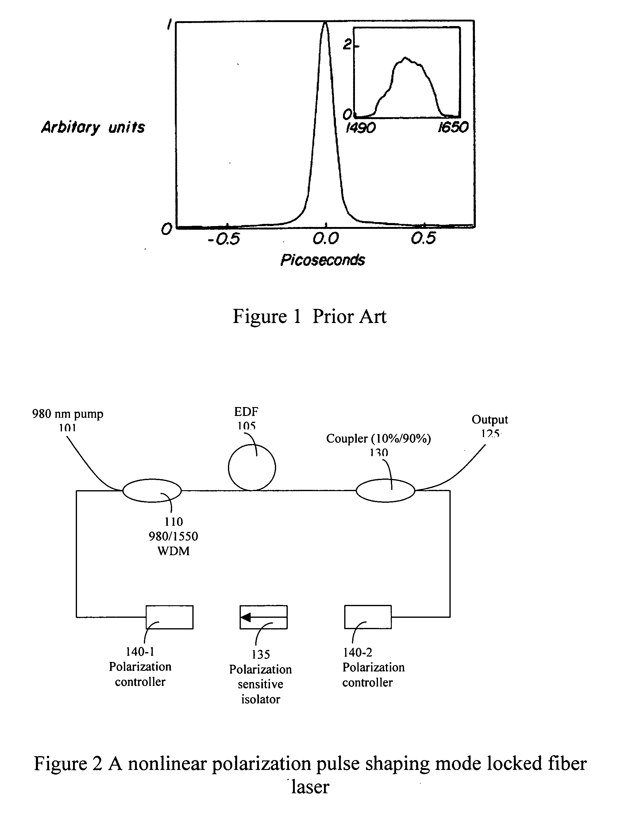
However, as that shown in FIG. 1, the waveform of the short pulse laser still present distorted pulses and the laser so generated is not a transform-limited shape and still have limited applications in telecommunications since such laser pulse is not able to overcome the problems of the non-linearity and dispersion effects of the laser pulses during the transmission.
The distorted pulse shapes are caused by the unbalanced dispersion and the non-linearity of control for operating the laser at the positive net dispersion region.
For these reasons, the laser disclosed by Tamura et al. cannot achieve a higher laser transmission efficiency of the transformed-limited shape.

Method used


Image

  • Nonlinear polarization pulse shaping mode locked fiber laser
  • Nonlinear polarization pulse shaping mode locked fiber laser
  • Nonlinear polarization pulse shaping mode locked fiber laser

Examples


Embodiment Construction

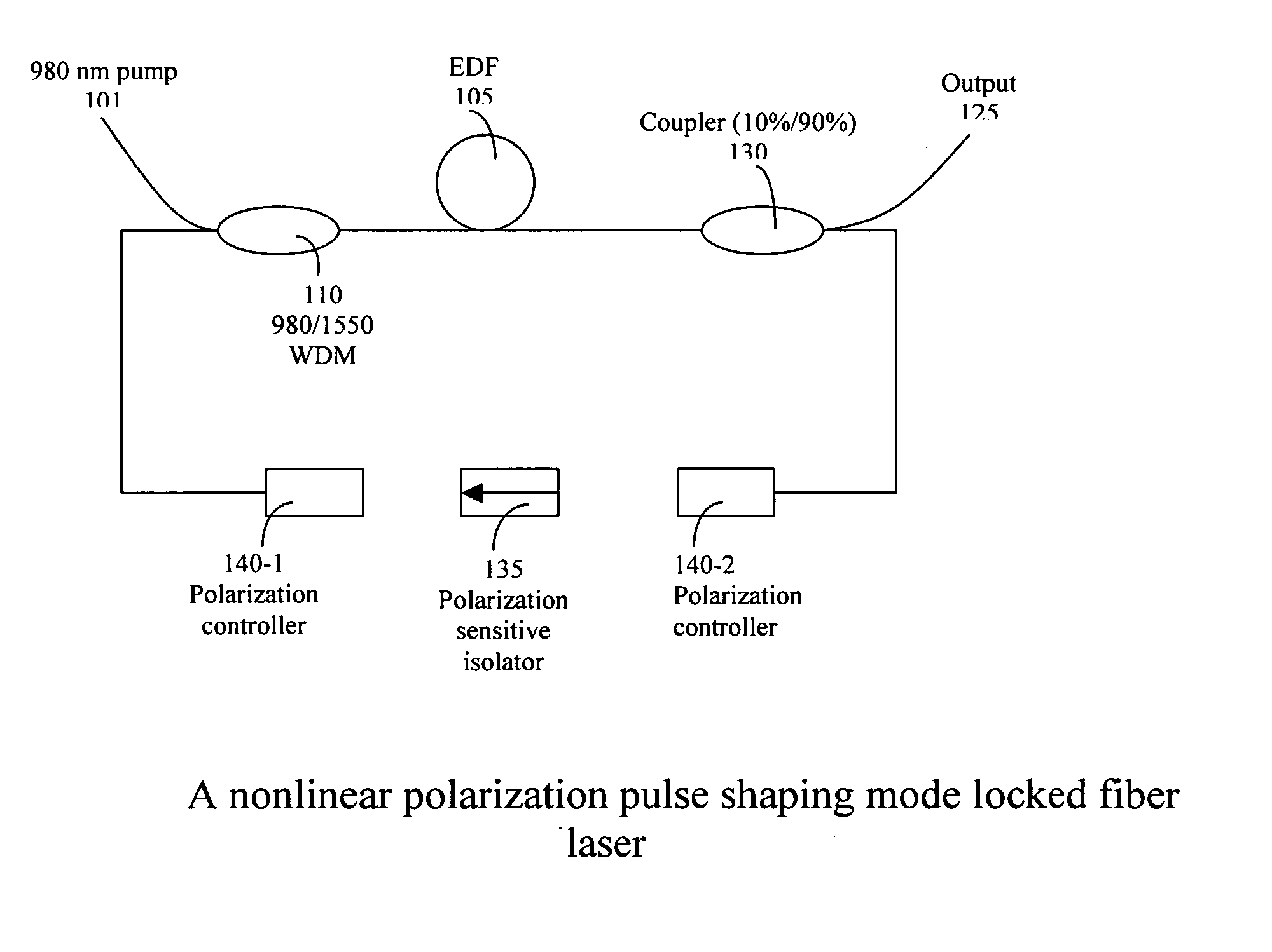
[0023] Referring to FIG. 2 for a schematic diagram of a nonlinear polarization pulse-shaping mode locked fiber laser 100 of this invention. The fiber laser is a ring structure laser that includes a gain medium (EDF) 105, a polarization sensitive isolator 135, polarization controllers 140-1 and 140-2, a 980 / 1550 WDM coupler 110, and an output coupler 130. One meter of Erbium doped fiber (EDF) 105 was used in the fiber laser as a gain medium and is used to amplify and compress the pulse width. The fiber has a high doping concentration (80 dB / m at 1530 nm) with a dispersion of −55 ps / nm / km. A 980 nm high power pump laser diode 101 coupled through a wavelength division multiplexer 110 is used to pump the EDF 105 to amplify the pulses circulating in the cavity. The rest of the cavity comprising a single mode (SM) fiber (17 ps / nm / km) 115 having a length about three meters and an HI 1060 fiber 120 commercially provided by Corning as standard fiber with dispersion 14 ps / nm / km at 1550 nm hav...


PUM


Abstract

A fiber laser cavity that includes a laser gain medium for receiving an optical input projection from a laser pump. The fiber laser cavity further includes a positive dispersion fiber segment and a negative dispersion fiber segment for generating a net negative dispersion for balancing a self-phase modulation (SPM) and a dispersion induced pulse broadening / compression in the fiber laser cavity for generating an output laser with a transform-limited pulse shape.

Description

[0001] This Formal Application claims a Priority Date of Apr. 12, 2004 benefit from a Provisional Patent Application 60 / 560,984 filed by the same Applicant of this Application.FIELD OF THE INVENTION [0002] The present invention relates generally to apparatuses and methods for providing short-pulsed mode-locked fiber laser. More particularly, this invention relates to new configurations and methods for providing a nonlinear polarization pulse-shaping mode-locked fiber laser with improved and better controllable pulse shapes. BACKGROUND OF THE INVENTION [0003] Conventional technologies of generating short pulse mode-locked fiber laser are still confronted with technical difficulties and limitations that the pulse shapes of the short-pulse laser cannot be properly and conveniently controlled. The difficulty is even more pronounced when the pulse width is further reduced. There is an urgent demand to resolve these technical difficulties as the broader applications and usefulness of the ...

Claims


Application Information

Patent Timeline
IPC IPC(8): H01S3/067H01S3/098H01S3/30
CPCH01S3/06712H01S3/1112H01S3/06791
Inventor LIU, JIAN
Owner POLARONYX
Learn More