Image display apparatus

a technology of image display and apparatus, which is applied in the direction of lighting and heating apparatus, television systems, instruments, etc., can solve the problems of reducing affecting unable to achieve the effect of improving so as to improve the efficiency of the illumination optical system, increase the amount of light passage, and improve the effect of the efficiency of the image display apparatus

Active Publication Date: 2005-10-27
MAXELL HLDG LTD
View PDF5 Cites 125 Cited by
  • Summary
  • Abstract
  • Description
  • Claims
  • Application Information

AI Technical Summary

Benefits of technology

[0012] Additionally, for instance, if the liquid-crystal panel 2 in the above example is a very small reflective mirror element, the polarizing conversion element of the illumination optical system is unnecessary. In this case, the relationship between the size (area) of the light source image of the LED element 1, formed near the exit side of the second lens array 7, and the maximum cross-sectional area of the optical path of the light passing through the lens cells of the second lens array 7, appears as in FIG. 2C. That is to say, an aperture 42′ that forms the maximum cross-sectional area of the optical path equals to the aperture 41 showing the profile shape of a lens cell of the second lens array 7. In this case, therefore, the light source image 44 becomes smaller than the aperture 42′ (41), a region not used (i.e., not permitting light to pass through) exists in the aperture 42′ (41), and thus the optical system decreases in efficiency.
[0013] With the above conventional technological problems in view, the present invention was made in order to enable the optical system of an image display apparatus to be improved in efficiency by improving the usage rate of light in the illumination optical system of the image display apparatus.
[0015] In order to solve the above problems, the present invention provides an image display apparatus for irradiating light from a light source unit with LED-based light-emitting portions onto image display elements and thus forming an optical image based on image signals; wherein a cross-sectional size or shape of the flux of light that have formed a light source image of each LED-based light-emitting portion is converted by anamorphic optics, such as collimator lenses, into a size or shape appropriate for an aperture in the portion of the light source image that permits the flux of light to pass through in an optical system for light-Irradiating the image display element(s), and the amount of passage of the light is increased by, for example, converting an aspect ratio of the cross section of the fluxes. The anamorphic optics improves efficiency of the image display apparatus in its illumination optical system by increasing the amount of passage of the light.
[0016] According to the present invention, it is possible to provide an image display technique that enables display of bright images.

Problems solved by technology

During the substantiation of the projection image display apparatus employing LEDs or other light-emitting elements as an LED light unit, it is difficult to obtain sufficient luminance for projected images since the amount of exit light flux per light source is very small, compared with that of an existing light source such as a high-pressure mercury lamp.
However, as more fluxes are condensed, the condensing angle of the fluxes will increase and the resulting decrease in the efficiency of the optical system for projection will consequently disable a projected image to be made bright.
Although the improvement of the illumination optical system in efficiency is required in order to satisfy that requirement, the light-emitting portions of the LED light sources are too large to be called spot light sources, and this is a hindrance to the improvement of the illumination optical system in efficiency.

Method used


Image

  • Image display apparatus
  • Image display apparatus
  • Image display apparatus

Examples


first embodiment

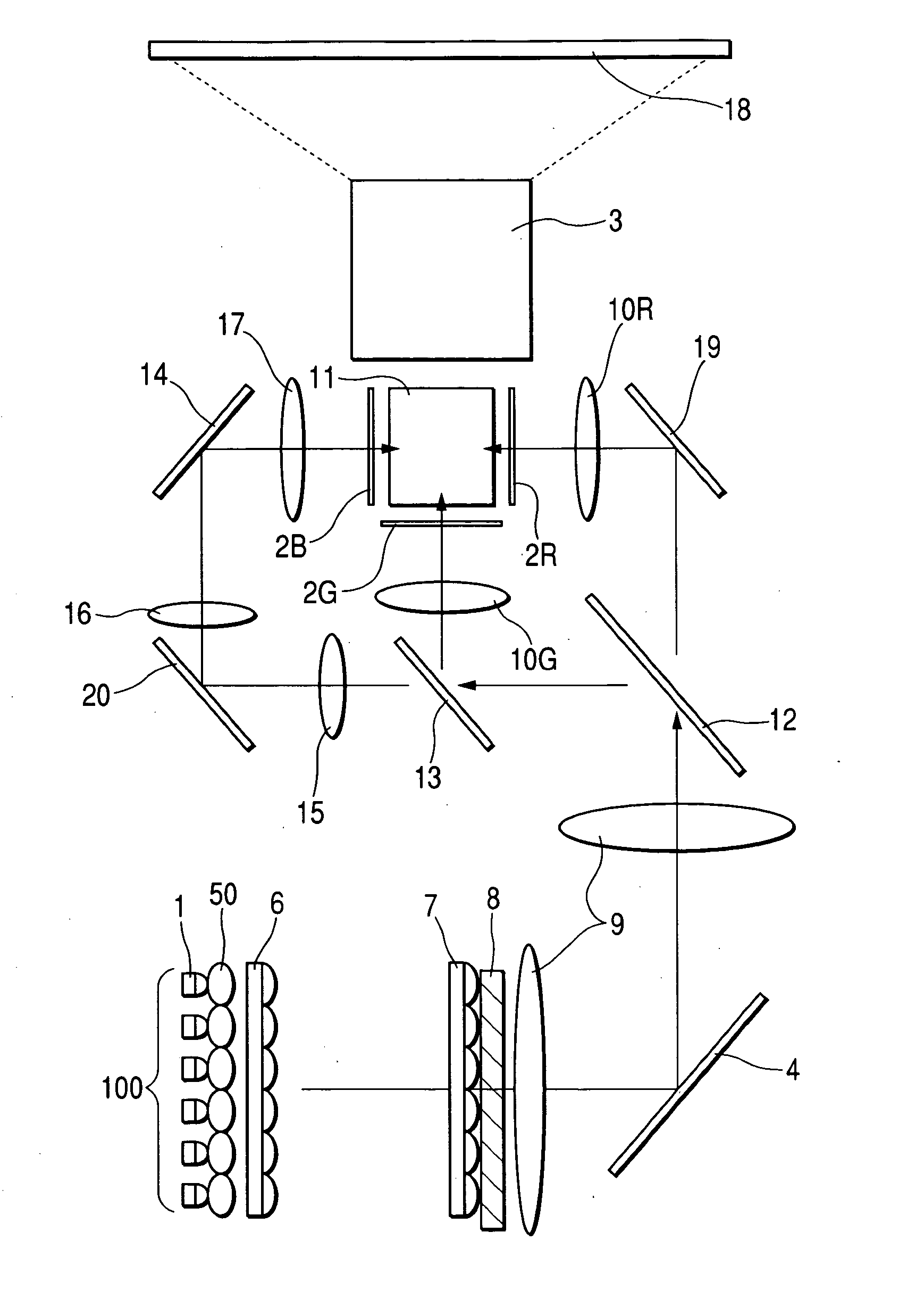
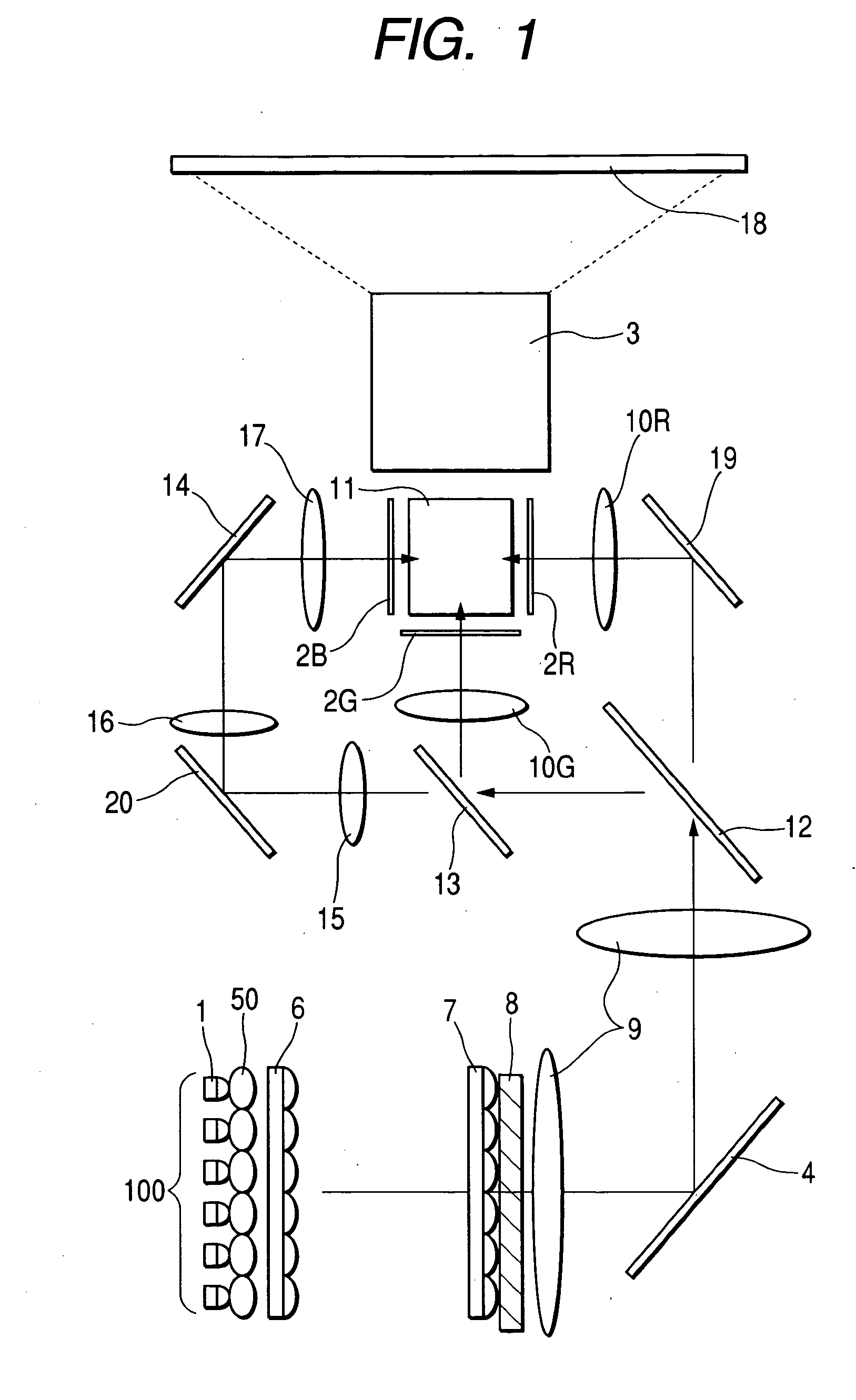
[0027]FIG. 1 is a diagram showing a configuration of a projection image display apparatus as a first embodiment of the present invention.

[0028] In FIG. 1, reference number 1 denotes an LED element having a light-emitting diode (LED) portion, and 100 a light source unit formed as a two-dimensional array of plural LED elements 1. Each LED element 1 has a collimator lens 50 for condensing light divergent from an LED portion (not shown) of an LED chip and introducing the light into an optical system for illumination. The collimator lens 50 forms anamorphic optics. Symbols 2R, 2G, and 2B denote transmissive liquid-crystal panels that are image display elements associated with the three primary colors of light, namely, red, green, and blue, respectively. Hereinafter, red light, green light, and blue light are referred to as R-light, G-light, and B-light, respectively. These liquid-crystal panels activate an image signal driver (not shown) to perform light intensity modulations responsive...

second embodiment

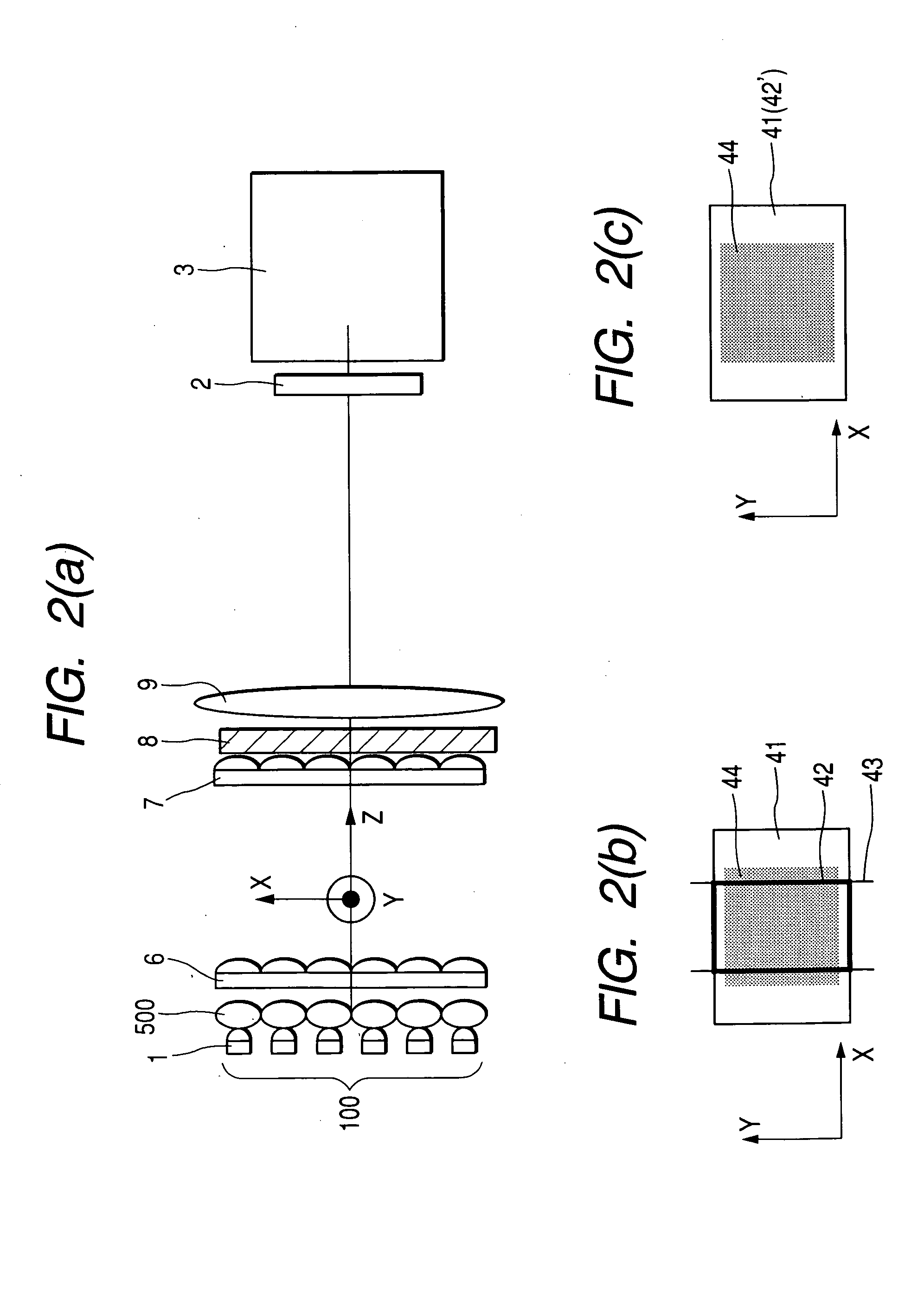
[0055] Although the above first embodiment uses the LED elements 1 adapted to directly emit light forward, a second embodiment employs reflective LED elements that each emit light forward after reflecting via a reflector the light emitted from an LED portion of the LED element. In addition, the reflector of the reflective LED element and a collimator lens disposed in front thereof constitute anamorphic optics. Thus, the light source image of the reflective LED element that is formed near the exit side of a second lens array 7 is endowed with a shape that almost agrees with a vertically long rectangular shape of an aperture 42 formed under restrictions on a range of incidence in a transverse direction at a unit prism unit of a polarizing conversion element 8.

[0056]FIG. 5 is a diagram showing a second embodiment of anamorphic optics. The anamorphic optics shown in the present embodiment is used in lieu of the anamorphic optics constituted by the collimator lenses 50 in the first embo...

third embodiment

[0062] Another example of using reflective LED elements is described as a third embodiment of the present invention below.

[0063] In the above second embodiment using reflective LED elements, a light source is constituted by each reflective LED element and a reflector provided at a rear side thereof, and anamorphic optics is constituted by the reflector and a collimator lens provided in front of the light source. In the present third embodiment, however, each reflective LED element has an integrally formed reflector at its rear side, a collimator lens provided in front is formed of the light-transmissive transparent resin used to seal a light-emitting portion of the reflective LED element, and anamorphic optics is constituted by the collimator lens formed of the foregoing transparent resin, and by the reflector.

[0064]FIG. 6 is a diagram showing the anamorphic optics used in the above third embodiment. A projection image display apparatus similar to that of the first embodiment is c...


PUM


Abstract

A technique is provided that improves the usage ratio of light in the illumination optical system of an image display apparatus. The cross-sectional size or shape of the flux of light that has formed a light source image of an LED-based light-emitting section is converted by anamorphic optics, such as collimator lens, into a size or shape appropriate for an aperture in the portion that permits the flux of the light source image to pass through, in an optical system leading to an image display element(s), and thus the quantity of fluxes of light passed through the aperture is increased.

Description

CLAIM OF PRIORITY [0001] The present application claims priority from Japanese application serial no. P2004-126852, filed on Apr. 22, 2004, the content of which is hereby incorporated by reference into this application. BACKGROUND OF THE INVENTION [0002] The present invention relates to an image display technique intended to display images by irradiating light from light sources onto image display elements and forming an optical image. More particularly, the invention is concerned with a technique intended for displaying bright images. [0003] Known examples of projection image display apparatus include a liquid-crystal projector that irradiates light from a light source onto a liquid-crystal panel such as an image display element, and projects an image in enlarged form on the liquid-crystal panel. [0004] A great number of types of products (projection image display apparatus) applying one or multiple lamps and capable of supplying large electric power to the light source(s) in order...

Claims


Application Information

Patent Timeline
IPC IPC(8): G02F1/13G02B27/09G02F1/13357G03B21/00G03B21/14G03B21/20
CPCG02B27/0911G02B27/0961Y10S362/80H04N9/3152G03B21/2033G02B27/0994
Inventor YAMASAKI, FUTOSHIYATSU, MASAHIKO
Owner MAXELL HLDG LTD
Why Eureka
Try Eureka