
Body fluid testing device

a body fluid and testing device technology, applied in the direction of measuring tapes, instruments, diagnostic recording/measuring, etc., can solve the problems of pain, infection, hematoma and other bleeding complications, and the inability to repeat direct vascular blood sampling on a routine basis, so as to achieve the effect of improving the concept of test tape meters

Active Publication Date: 2005-10-20
ROCHE DIABETES CARE INC
View PDF98 Cites 155 Cited by
  • Summary
  • Abstract
  • Description
  • Claims
  • Application Information

AI Technical Summary

Benefits of technology

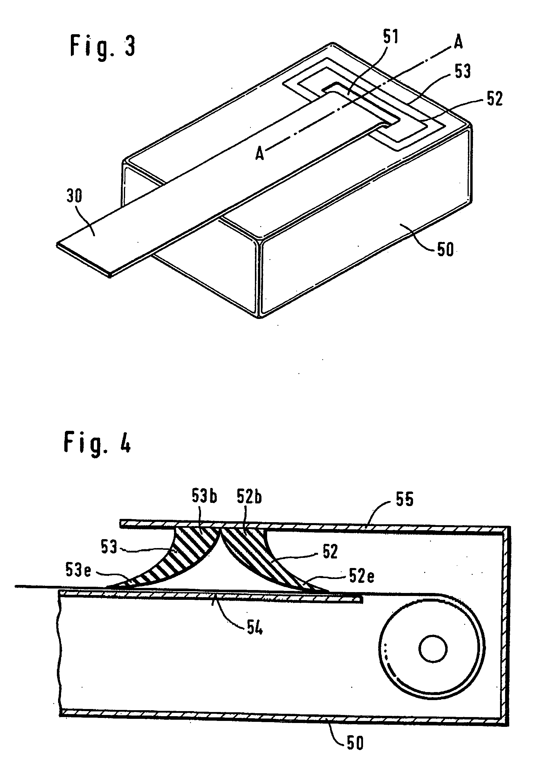
[0017] According to the present invention, it was found that the concept of test tape meters can be highly improved. A test media tape is employed on which the individual test media are spaced one from the other so that free tape portions are located between successive test media. Such a test media tape is contained in a supply container which shelters the test media tape against humidity. Test media can be taken out of the container via an opening by using the tape as a transporting means. The test media which are still located within the supply container are protected against humidity by using a sealing means for sealing the opening of the container while a free tape portion is located between the sealing means and a surface of the supply container. This type of sealing enables very practical testing devices which can provide numerous test media without the need for the user to load the testing device with separate individual test elements.
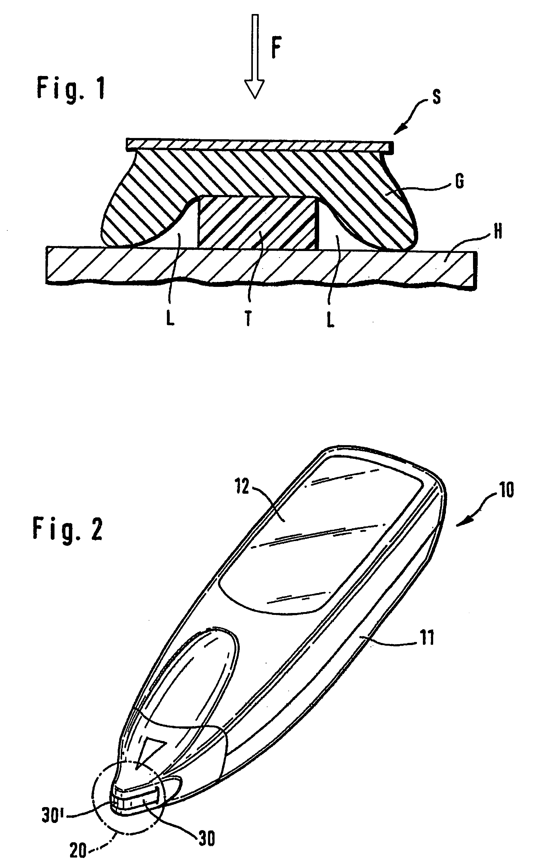
[0018] Due to the spacing of the test media, the material of the free tape portion can be chosen mostly independent from the test media material to achieve a proper sealing with the described sealing means. It has been shown that tape materials as e.g., plastics for audio cassettes are well suited for this purpose. Suitable tape materials are plastic foils from polyester, polycarbonate, cellulose derivatives, and polystyrene. It is, however, preferred to choose non-hygroscopic materials which do not transport water or water vapour to a high degree. According to this, tapes without free tape sections between successive test media cannot be sealed properly since the test media material is porous and thus would allow humidity to flow into the supply container even when the tape is sealed according to the present invention. Further, the thickness of the tape in the free tape portion is an important parameter to control proper sealing. It has been shown by the inventors of the present invention that leakage of humidity into the storage housing decreases with decreasing tape thickness. While there are a number of interacting parameters, the particular effect of the tape thickness can be seen from FIG. 1. The tape (T) is located between a sealing means (S) having a deformable gasket (G) and a surface of the container housing (H). The sealing means applies pressure in the direction of the housing, thus pressing the gasket onto the tape and housing surface. The gasket is stronger compressed in the region of the tape as it is right and left from the tape. The leakage regions (L) which are not filled by tape or gasket material allow influx of humid air. Decreasing the tape thickness hence reduces the cross section of the leakage regions. It has been shown that a tape having a thickness below 100 micrometers is well suited to limit humidity influx into the housing even if the gasket is relatively rigid. Even more preferred are tape thicknesses below 50 micrometers.
[0020] Further, it can be understood with view to FIG. 1 that an increasing flexibility of the gasket reduces humidity influx. It has shown that gaskets with a shore hardness (A) of less than 70, preferably in a range of 30 to 50 are well suited. The shore hardness (A) is defined by DIN 53505 (June 1987). Gasket materials which are well suited to practice the present invention are thermoplastic elastomers. Especially suited are such elastomeres which comprise polystyrene as the hard component and polymerisates of butadiene or isoprene as the soft component. Suitable gasket materials can be obtained under the tradenames Kraton D, Kraton G and Cariflex TR from Shell and Solprene from Philips.
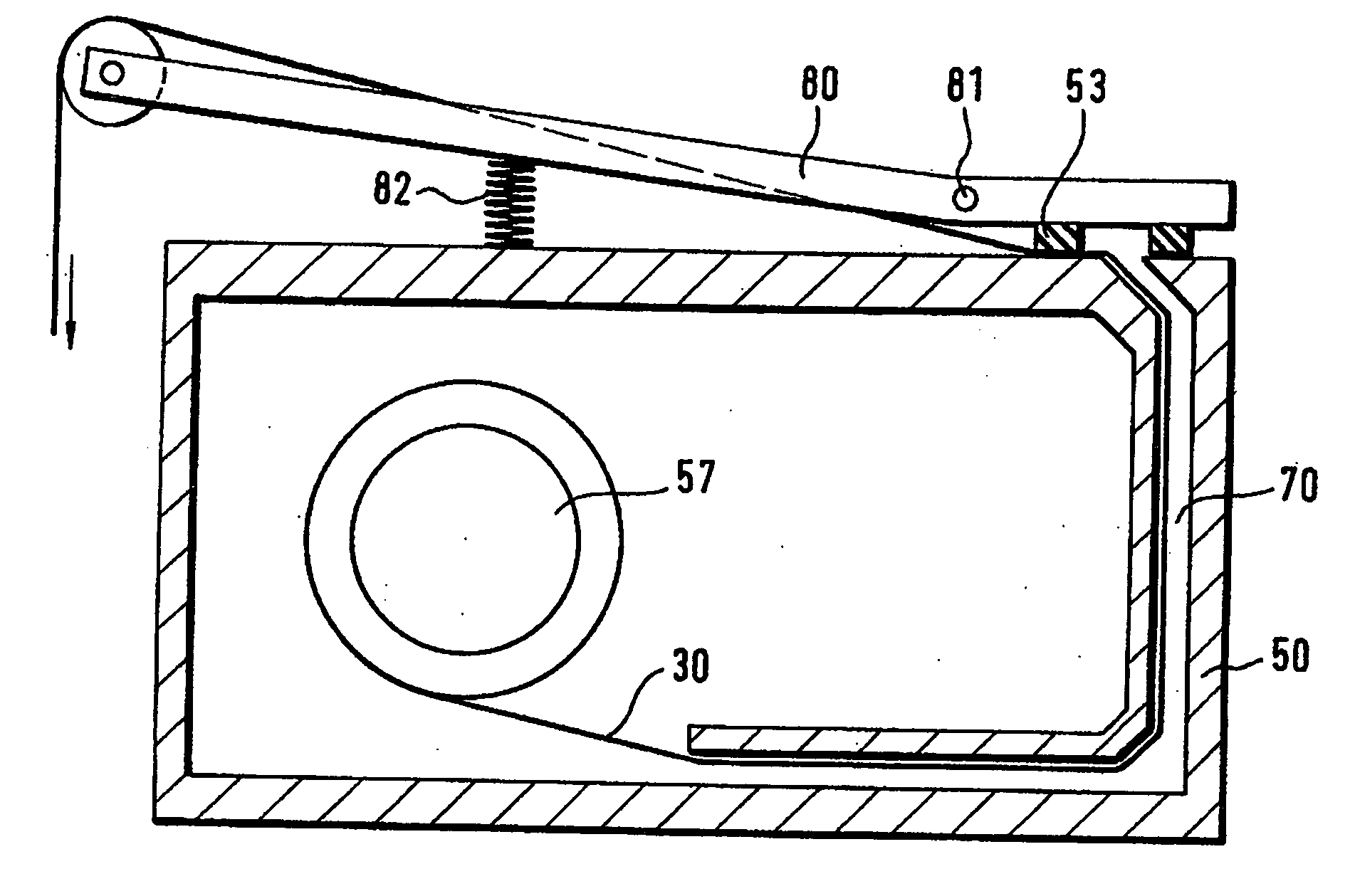
[0023] The sealing means further comprises a pressure means that serves to apply pressure to the sealing means body so as to achieve the sealing. Such pressure means are e.g., coil springs, pneumatic actuators, motors, electromagnets, compressed materials, or stressed materials. From the preferred embodiments, it will become clear that in particular elastic sealing means which in their rest position press onto the sealing means body are easy and cheap to manufacture.
[0028] In accordance with one aspect of the present invention, there is provided a body fluid testing device for analyzing a body fluid. The testing device includes a test media cassette that includes a test media tape adapted to collect the body fluid. The cassette includes a supply portion that stores an uncontaminated section of the test media tape. A storage portion for storing a contaminated section of the test media tape may be further employed. Contrary to the supply portion which is designed to shelter the test media tape from humidity from the surrounding environment, it is preferred to design the storage section for contaminated tape to be open to some extent so that the test media which are soaked with sample can dry out. Such an open design may be realized by a plastic container having slits or recesses for gas exchange with the surrounding environment.
[0037] In a particular embodiment, a supply reel is disposed in the supply portion of the housing around which the uncontaminated section of the test media tape is wrapped, and a storage reel is disposed in the storage portion of the housing around which the contaminated section of the test media tape can be wrapped. In embodiments which employ a reel for storing uncontaminated test media tape, it is preferred that the axis of this supply reel does not penetrate the supply container housing to avoid the leakage of humid air into the container.

Problems solved by technology

However, such direct vascular blood sampling can have several limitations, including pain, infection, and hematoma and other bleeding complications.
In addition, direct vascular blood sampling is not suitable for repeating on a routine basis, can be extremely difficult, and is not advised for patients to perform on themselves.
However, the fingertip also has a large concentration of nerve endings, and lancing the fingertip can therefore be painful.
This can be especially inconvenient when the person is away from home, such as at a restaurant.
The use of expired test elements may create false readings, which can result in improper treatment of the patient, such as improper insulin dosages for diabetics.
These test systems are, however, designed to be used in the environment of automated laboratory systems and are therefore not suited for patient self testing.
A number of practical problems are, however, still unsolved when relying on the device described in DE 198 19 407.
Test media used for blood glucose testing as well as for other analytes are prone to deterioration by humidity from the environmental air.
It is therefore a serious problem to keep unused test media free from humidity to avoid deterioration which would lead to incorrect analytical results.
The automated analytical instruments of U.S. Pat. No. 5,077,010 have a high throughput and therefore the required onboard stability is short (typically one or two days only).
Contrary to that, the required onboard stability in the home diagnostic market is much longer.
The situation, however, may be even worse considering that the patient may have a second meter and uses the present meter only from time to time.
It has been shown that the type of sealing as disclosed in U.S. Pat. No. 5,077,010 is insufficient to achieve the onboard stability as required in the home monitoring environment.

Method used


Image

  • Body fluid testing device
  • Body fluid testing device
  • Body fluid testing device

Examples


Embodiment Construction

[0071] For the purposes of promoting and understanding of the principles of the invention, reference will now be made to the embodiments illustrated in the drawings and specific language will be used to describe the same. It will nevertheless be understood that no limitation of the scope of the invention is thereby intended, such alterations and further modifications in the illustrated device, and such further applications of the principles of the invention as illustrated therein being contemplated as would normally occur to one skilled in the art to which the invention relates. It will be apparent to those skilled in the art that some of the features which are not relevant to the invention may not be shown for the sake of clarity.

[0072] The humidity sealing principle is shown in FIG. 1. On the housing surface (H) which preferably has a low roughness the test-carrier-tape (T) is pressed by the sealing material (G). The sealing force (F) presses the flexible gasket around the test m...


PUM

PropertyMeasurementUnit
thicknessaaaaaaaaaa
shore hardnessaaaaaaaaaa
thicknessesaaaaaaaaaa

Abstract

Body fluid testing device for analyzing a body fluid comprises a test media tape adapted to collect the body fluid. The test media tape comprises a tape and test media portions. A free tape portion without test medium is located between successive test media portions. The testing device further comprises a supply portion. The supply portion comprises a housing in which uncontaminated test media tape is contained. The housing further has an opening for withdrawing test media tape from the housing. The testing device further has a sealing means for closing the opening against the surrounding. A free tape portion of the test media tape is located between a wall of the housing and the sealing means when the sealing means closes the opening. Further aspects concern a test media cassette with sealing means and a method for providing test media while holding them sealed against humidity during onboard storage.

Description

REFERENCE TO RELATED APPLICATIONS [0001] The present application is a continuation of International Patent Application No. PCT / EP2003 / 014708 filed Dec. 22, 2003, which claims foreign priority to European Patent Application No. 02 028 894.0 filed Dec. 23, 2002, which are hereby incorporated by reference in their entirety.BACKGROUND OF THE INVENTION [0002] The present invention relates to body fluid testing devices and more specifically, but not exclusively, concerns a body fluid testing device that incorporates a test media cassette which contains test media used to test body fluid. General Fluid Testing [0003] The acquisition and testing of body fluids is useful for many purposes and continues to grow in importance for use in medical diagnosis and treatment and in other diverse applications. In the medical field, it is desirable for lay operators to perform tests routinely, quickly and reproducibly outside of a laboratory setting, with rapid results and a readout of the resulting t...

Claims


Application Information

Patent Timeline
Patent Type & Authority Applications(United States)
IPC IPC(8): G01N35/00
CPCG01N35/00009G01N33/48764G01N2035/00089G01N35/00029
Inventor RUHL, WERNERZIMMER, VOLKERSCHREM, HUGO
Owner ROCHE DIABETES CARE INC
Learn More