Refractive projection objective
a technology of objective and refractive, which is applied in the field of refractive projection objective, can solve the problems of limited availability of fluoride materials in particular, and achieve the effects of reducing material use, high numerical aperture, and reducing production costs
- Summary
- Abstract
- Description
- Claims
- Application Information
AI Technical Summary
Benefits of technology
Problems solved by technology
Method used
Image
Examples
third embodiment
[0066] For the third embodiment according to FIG. 3, and Table 3, Table 3a gives the maximum incidence / exit angle measured in the optically thin medium (gas) Imax in degrees for each surface as in Table 3, plus the sine of the angle SINImax, which is directly comparable to the NA value. While the entrance and exit surface 49, 50 of the plane-parallel cover plate necessarily exceed Imax of 60 degrees with Imax=60, 70 degrees and the exit Imax of the last lens 47, 48 very nearly reaches the limit with Imax (48)=59.99 degrees. Here, exactly one lens surface 31 exceeds the limit, too, with Imax=60.51 degrees.
[0067] It is a negative meniscus lens situated between the object plane O and the system aperture 36, with the concave imageward surface 31 showing this extreme exit angle Imax=60.51 degrees, all this being preferred properties either singularly or in combination.
fourth embodiment
[0068] The fourth embodiment according to FIG. 4 and Table 4 has similar Imax properties shown in Table 4a. Cover plate 57, 58 closing the projection objective from the atmosphere at the image plane 60, where a wafer to be exposed is located, necessarily has an lmax=62 degrees, SIN Imax=0.88 equivalent to the (image side) numerical aperture NA. The exit surface 56 of the next lens 55, 56 also has an Imax (56)=61.28 degrees and also incident surface 53 of the third refractive element from the image plane has an Imax (53)=52.60 degrees exceeding 50 degrees.
[0069] Now, for compensation, it is provided by optical design choice, that also surfaces 33 and 34 in the lens arrangement between object plane 0 and system aperture 40 have Imax (33)=64.50 degrees and Imax (34)=61.22 degrees. Neighboring surfaces repeatedly lend themselves to this use of high Imax angles. Additional compensation is obtained by surfaces having Imax in the range between 50 degrees and 60 degrees. Neighboring surface...
sixth embodiment
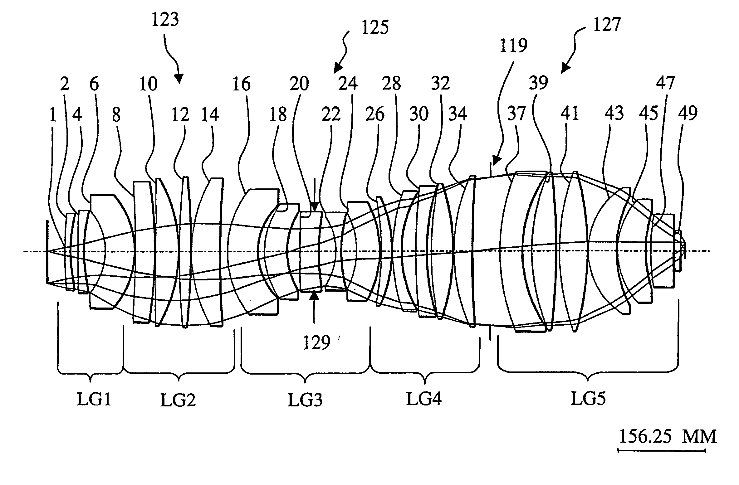
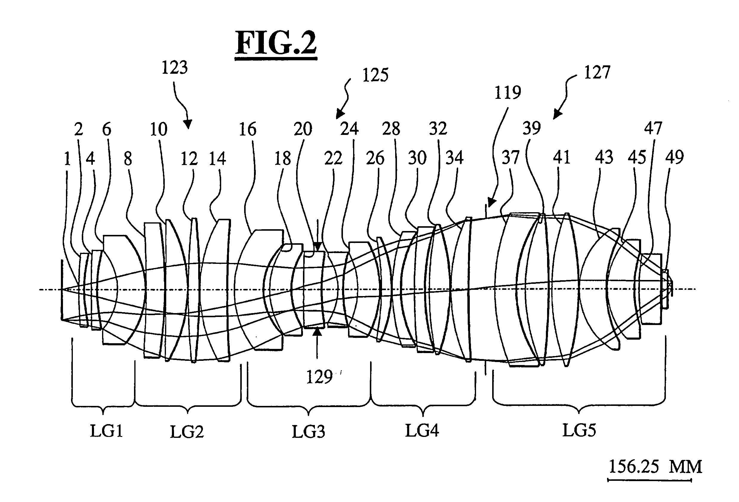
[0072] FIG. 6, Table 6 and Table 6a shows Imax to exceed 60 degrees at the four surfaces of the two refractive elements next to the image plane 54, and specifically at surface 25 Imax (25)=65.26 degrees. This is situated at a location preferred by the inventors: between object plane 0 and aperture plane 37, on an image wise concave plane, thus being an exiting angle, and within negative lens group LG3, which consists of the four lenses next to the waist, which is effected by the locally minimum beam diameter (see data in sixth column of Table 6) at surface 23 of negative lenses 22, 23.
[0073] Additionally, surfaces 39 and 40 of lenses 38, 39 and 40, 41 show Imax (39)=58.11 degrees and Imax (40)=52.80 degrees as an assisting correction means with an Imax in the range from 50 degrees to 60 degrees. All the other surfaces within the object have well reduced Imax values, as normally preferable, with only surface 26 next to 25 reaching Imax (26)=45.11 degrees.
[0074] Besides, only the mos...
PUM
| Property | Measurement | Unit |
|---|---|---|
| exit angle | aaaaa | aaaaa |
| exit angle | aaaaa | aaaaa |
| exit angle | aaaaa | aaaaa |
Abstract
Description
Claims
Application Information
 - R&D
- Intellectual Property
- Life Sciences
- Materials
- Tech Scout
- Unparalleled Data Quality
- Higher Quality Content
- 60% Fewer Hallucinations
Browse by: Latest US Patents, China's latest patents, Technical Efficacy Thesaurus, Application Domain, Technology Topic, Popular Technical Reports.
© 2025 PatSnap. All rights reserved.Legal|Privacy policy|Modern Slavery Act Transparency Statement|Sitemap|About US| Contact US: help@patsnap.com


