Air servo cylinder

a technology of air servo cylinder and cylinder body, which is applied in the direction of servomotors, fluid couplings, manufacturing tools, etc., can solve the problems of increasing the possibility of becoming obstacles to welding gun operation, electromagnetic noise, and air servo cylinder sputtering, so as to enhance the functionality and reduce the size of the air servo cylinder

Active Publication Date: 2005-10-20
SMC CORP
View PDF4 Cites 11 Cited by
  • Summary
  • Abstract
  • Description
  • Claims
  • Application Information

AI Technical Summary

Benefits of technology

[0007] The object of the present invention is to reasonably design and configure an air servo cylinder that is formed by integrall

Problems solved by technology

This has increased the possibility of becoming obstacles to operations of the welding gun even if the silencers are small protrusions, since the silencers are attached to the welding gun so as to protrude toward the outside.
Such a problem is not confined to welding guns for spo

Method used


Image

  • Air servo cylinder
  • Air servo cylinder
  • Air servo cylinder

Examples


Embodiment Construction

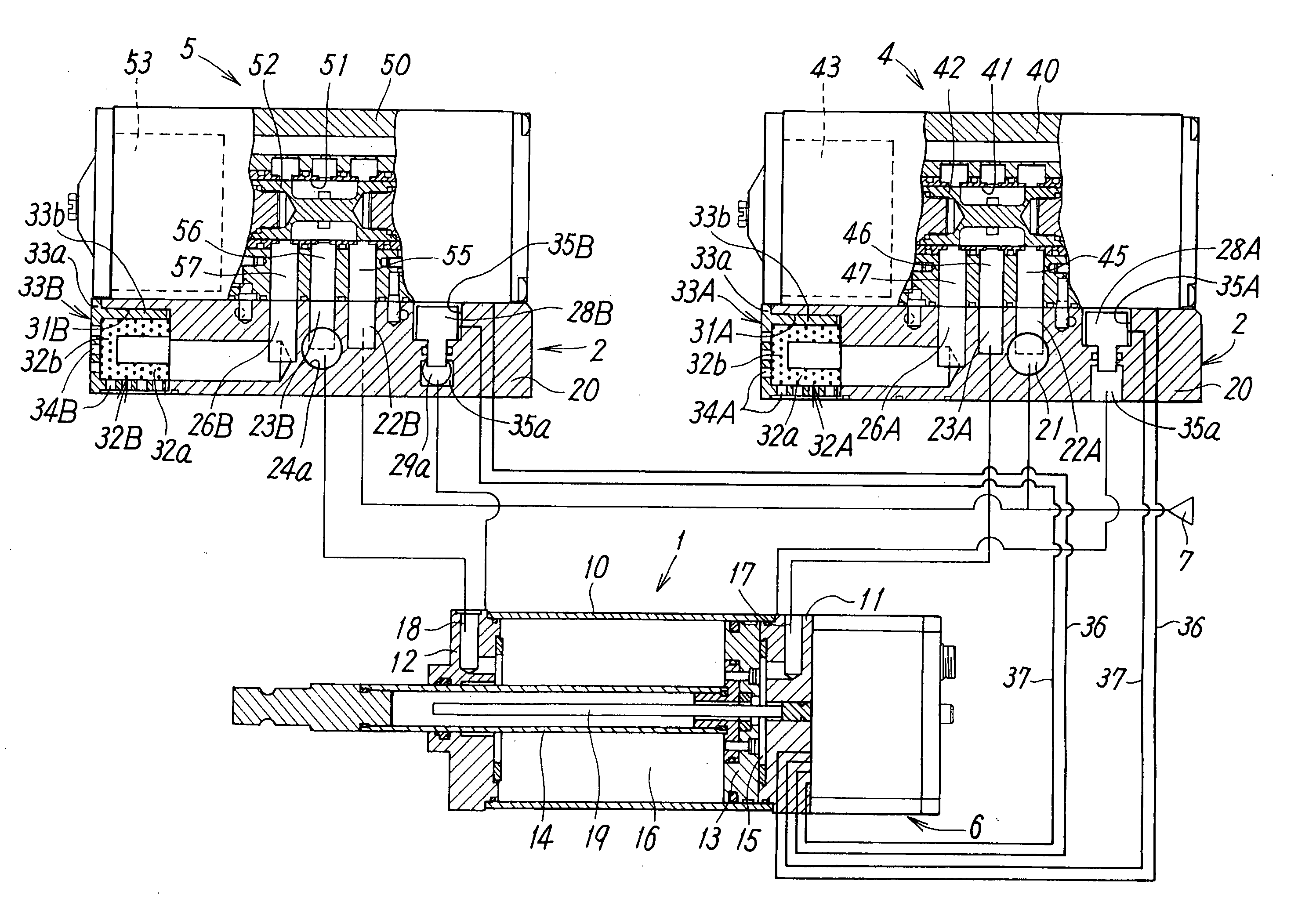
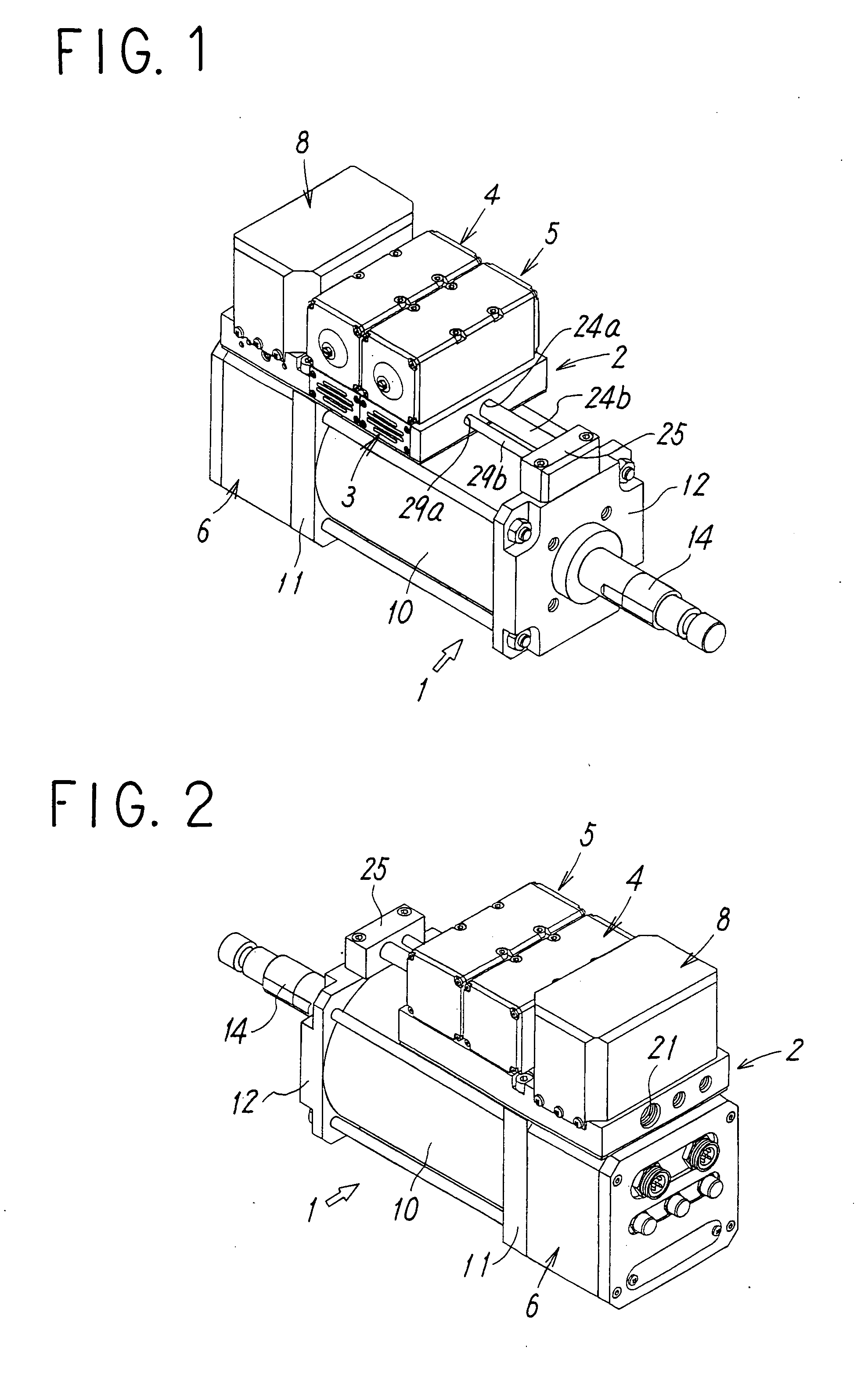
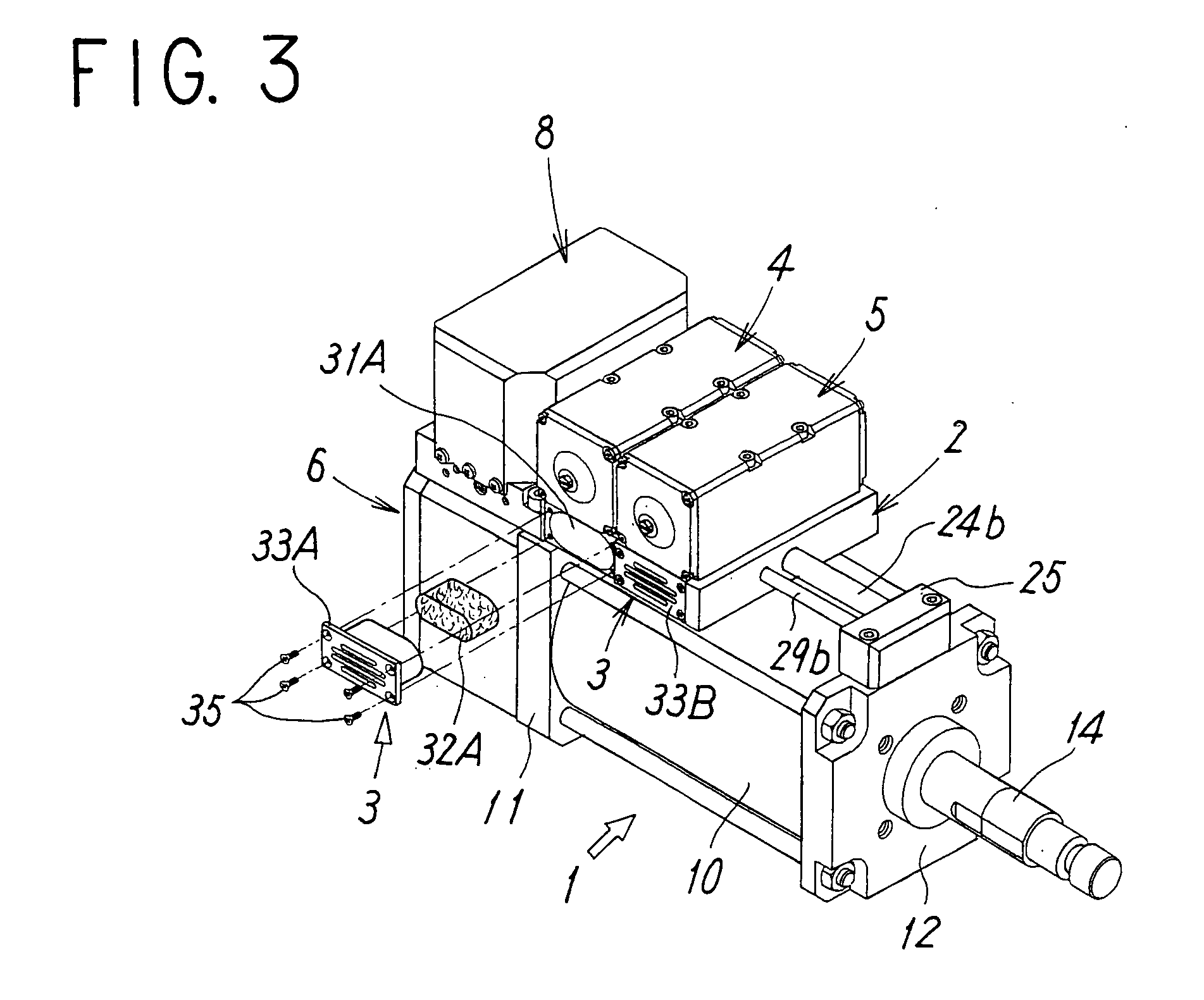
[0019] FIGS. 1 to 3 show external appearances of the air servo cylinder according to the present invention. This air servo cylinder is used as an actuator for driving a clamping mechanism for clamping workpiece to be welded, in a gun for spot welding.

[0020] Broadly speaking, the air servo cylinder is configured so that a first and second servo valves 4,5 are mounted on the side surface of the air cylinder 1 with a plate-shaped manifold block 2 therebetween; compressed air supply and discharge flow paths that connect the air cylinder 1 and each of the servo valves 4,5 are formed in the manifold block 2; and the air cylinder 1 is driven by the servo valves 4,5. Furthermore, a silencer 3, to be described later, for reducing exhaust noise is incorporated into the manifold block 2. On the end section of the manifold block 2, a controller 6 is provided on the undersurface thereof while an equalizing unit 8 is mounted on the top surface thereof.

[0021] As shown in FIG. 4, the air cylinder...


PUM


Abstract

In an air servo cylinder formed by integrally combining an air cylinder, servo valves, and a controller via a manifold block, there are provided, in the manifold block, air discharge flow paths for releasing, to the outside, compressed air discharged associated with operations of the servo valves. In each of the air discharge flow paths, a silencer for reducing exhaust noise is incorporated so as not to protrude from the manifold block to the outside.

Description

TECHNICAL FIELD [0001] The present invention relates to an air servo cylinder formed by integrally assembling an air cylinder and servo valves for controlling thereof, and more specifically, relates to an air servo cylinder applied to a spot welding gun, and usable for the clamping of workpiece to be welded, or the like. BACKGROUND ART [0002] A welding gun having a clamp mechanism for clamping workpiece to be welded during spot welding comprises an air servo cylinder formed by integrally assembling an air cylinder with servo valves, a controller for controlling the air cylinder, and the like. This welding gun is mounted on the tip of an arm of a robot for welding, and performs welding operation while being moved to various welding positions. Therefore, the requirements for the welding gun are small size, light weight, and compactness. [0003] Also, it is desirable for the welding gun to be capable of clamping workpiece while being moved in narrow spaces, so that it is necessary to pr...

Claims


Application Information

Patent Timeline
IPC IPC(8): B23Q3/06F15B15/14F15B11/06F15B13/00F15B15/20F16B2/06F16D31/02
CPCF15B15/202E04G21/3266E04G3/18E04G7/16
Inventor MATSUMOTO, DAISUKEFUJIWARA, NOBUHIROMIYACHI, HIROSHI
Owner SMC CORP
Why Eureka
Try Eureka