
Routing architecture

a routing architecture and routing technology, applied in the field of data communication, can solve the problems of notable limitations, dedicated switches consume a non-trivial amount of power, power consumption and heat dissipation issues may require attention, etc., to achieve the effect of reducing board space consumed and overall cost, improving power and cooling budgets

Inactive Publication Date: 2005-10-06
LUCENT TECH INC
View PDF19 Cites 4 Cited by
  • Summary
  • Abstract
  • Description
  • Claims
  • Application Information

AI Technical Summary

Benefits of technology

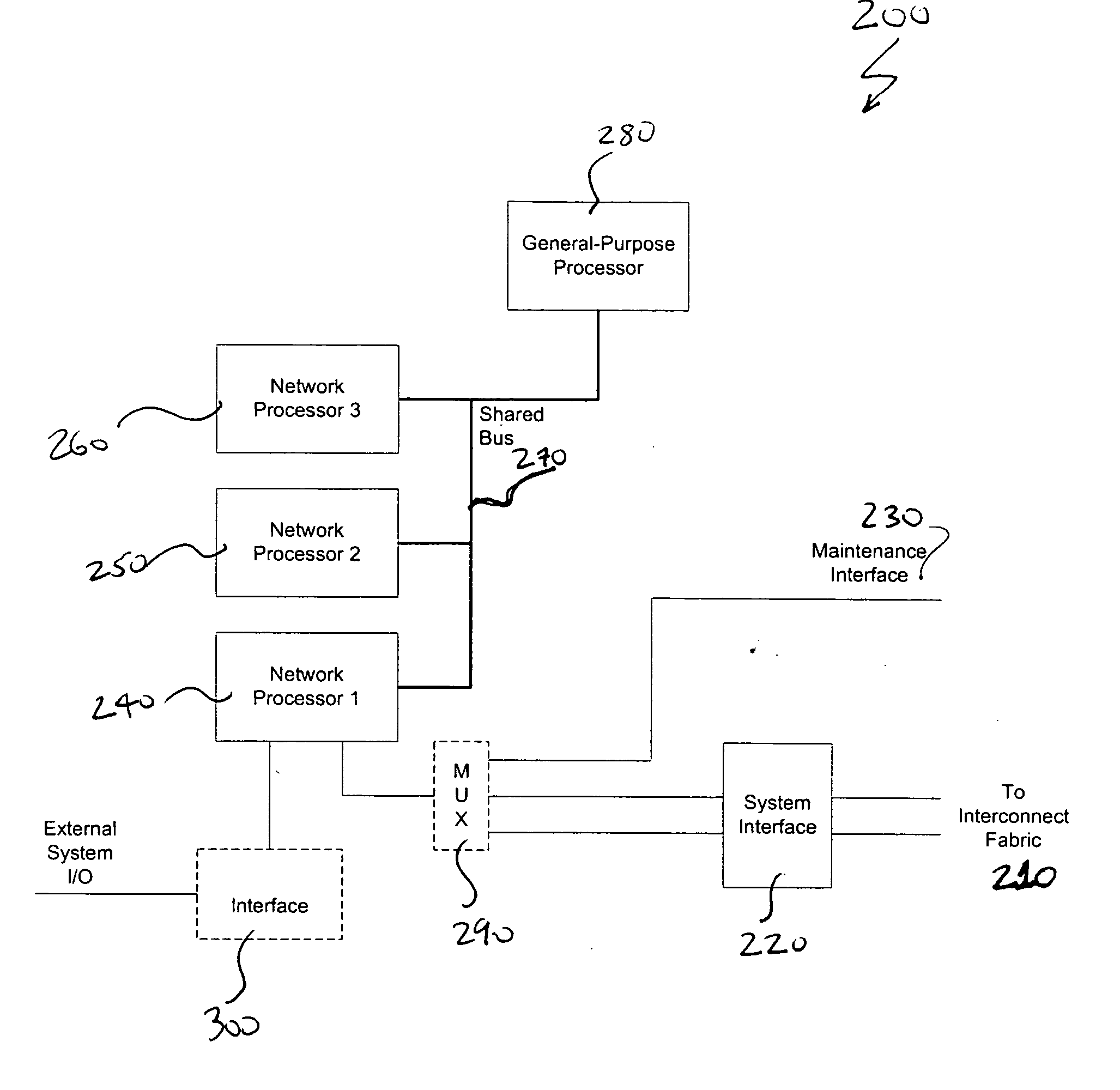
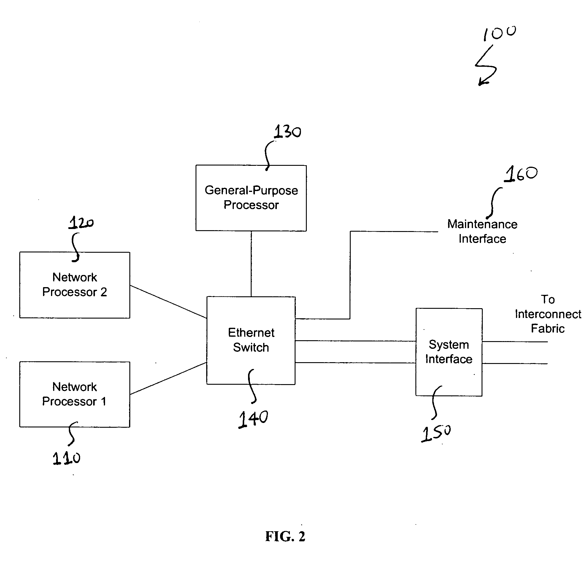
[0008] The present invention provides a routing architecture for improving power and cooling budgets, as well as reducing board space consumed and overall cost. More particularly, the present invention provides a communication node architecture for routing cell and / or packet information between application processors. The present invention realizes the communication node architecture without the need for a dedicated switching device, such as an Ethernet switch, for example. The communication node architecture may be deployed in numerous applications, including, for example, a radio node controller, base station controller, and a traffic-processing controller.

Problems solved by technology

While the use of a dedicated switch is effective, there are notable limitations.
Firstly, the dedicated switch consumes a non-trivial amount of power.
Consequently, power consumption and heat dissipation issues may require attention.
Moreover, the cost of each dedicated switch, and the space each consumes on the AP node's circuit board may also impact on the design and efficiency of the system.

Method used


Image

  • Routing architecture
  • Routing architecture
  • Routing architecture

Examples


Embodiment Construction

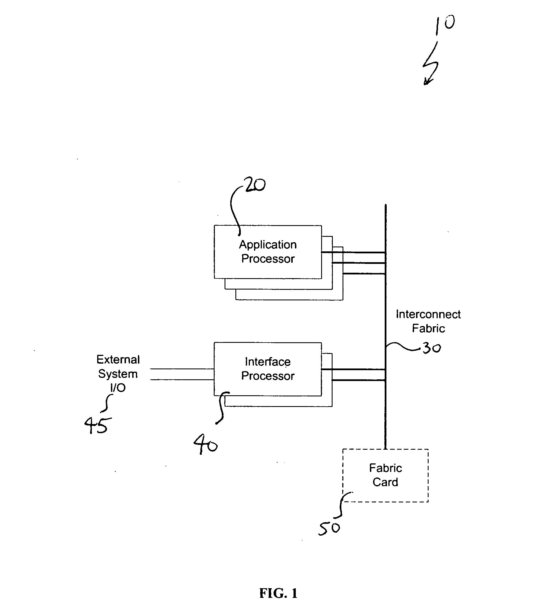
[0017] Referring to FIG. 1, a high-level block diagram of a digital communication system 10 is illustrated. As depicted, system 10 is capable of supporting various services, including the communication of voice and / or data traffic. More particularly, system 10 may enable wired and / or wireless communication applications.

[0018] To further serve these purposes, digital communication system 10 includes a plurality of Application Processing (“AP”) or communication nodes 20. Each of the nodes 20 perform a function(s) required by system 10 and may be-realized by a printed circuit board (“PCB”). The functions performed may include, for example, Bearer Transport Path Processing, Call Control, Operations and Maintenance. AP nodes 20 may be configured to execute the same function(s), and therefore may be realized using the same or similar design. In the alternative, each AP node 20 may serve a differing function(s), in part or in whole, depending on the requirements of system 10, and therefor...


PUM


Abstract

A digital communications system for processing at least one of cell and packet information. The digital communication system includes one or more communication nodes interconnected through a fabric. The communication node(s) has at least one network processing devices, one of which may be designated for receiving the cell and / or packet information, for determining a destination within the node for the cell and / or packet information, and for routing and / or forwarding the cell and / or packet information to the destination. Each communication node may also include a shared bus structure for coupling each of the network processing devices together, as well as an interface for coupling the designated network-processing device with the fabric to support communication between other communication nodes.

Description

FIELD OF THE INVENTION [0001] This invention relates to the field of telecommunications, and more particularly to data communications. BACKGROUND OF THE INVENTION [0002] Data communication is a reflection of life in the 21st century. Applications, such as e-mail and the Internet, has increasingly become mainstream. Moreover, a move is afoot for migrating voice traffic from circuit-switched type networks to packet-switched type networks in support of Voice over IP (“VoIP”) applications. Consequently, data traffic has continued to increase as acceptance and adoption of these applications continue to grow. [0003] With the continued expansion of data applications, there is a growing consumer demand for accurate wired and wireless high-speed access. Systems supporting data communication typically employ a number of Application Processing (“AP”) or communication nodes. These AP nodes may be driven by wired and wireless high-speed access, as well as VoIP applications. [0004] AP nodes are i...

Claims


Application Information

Patent Timeline
IPC IPC(8): H04L12/56
CPCH04L12/5601H04L49/107H04L2012/5665H04L49/256H04L49/1576B66C13/08B66C13/12
Inventor LOUGHRAN, KEVINSILVA, RUI ADELINOVELTRI, JOSEPH
Owner LUCENT TECH INC
Learn More