
Patterned grid element polarizer

a polarizer and grid element technology, applied in the field of polarizing optical elements, to achieve the effect of improving the image formed at the wafer

Inactive Publication Date: 2005-10-06
ASML HLDG NV
View PDF30 Cites 54 Cited by
  • Summary
  • Abstract
  • Description
  • Claims
  • Application Information

AI Technical Summary

Benefits of technology

This patent describes how improving the quality of images during lithography by controlling the polaization state of the illumination. By using wire grids with specific patterns designed for different applications, researchers hope to create better results when producing patterns through optical systems. Overall, this technology helps make more precise and accurate patterns during manufacturing processes.

Problems solved by technology

The technical problem addressed in this patent relates to improving the quality of images generated during the production of integrated circuits using advanced technology such as extreme ultraviolet (EUV) lithography. By utilizing a polarized illuminator, researchers hope to enhance the interference of diffracted rays and ultimately achieve better image formation at the wafer level.

Method used


Image

  • Patterned grid element polarizer
  • Patterned grid element polarizer
  • Patterned grid element polarizer

Examples


Embodiment Construction

[0021] Reference will now be made to the drawings in which the various elements of the present invention will be given numerical designations and in which the invention will be discussed so as to enable one skilled in the art to make and use the invention.

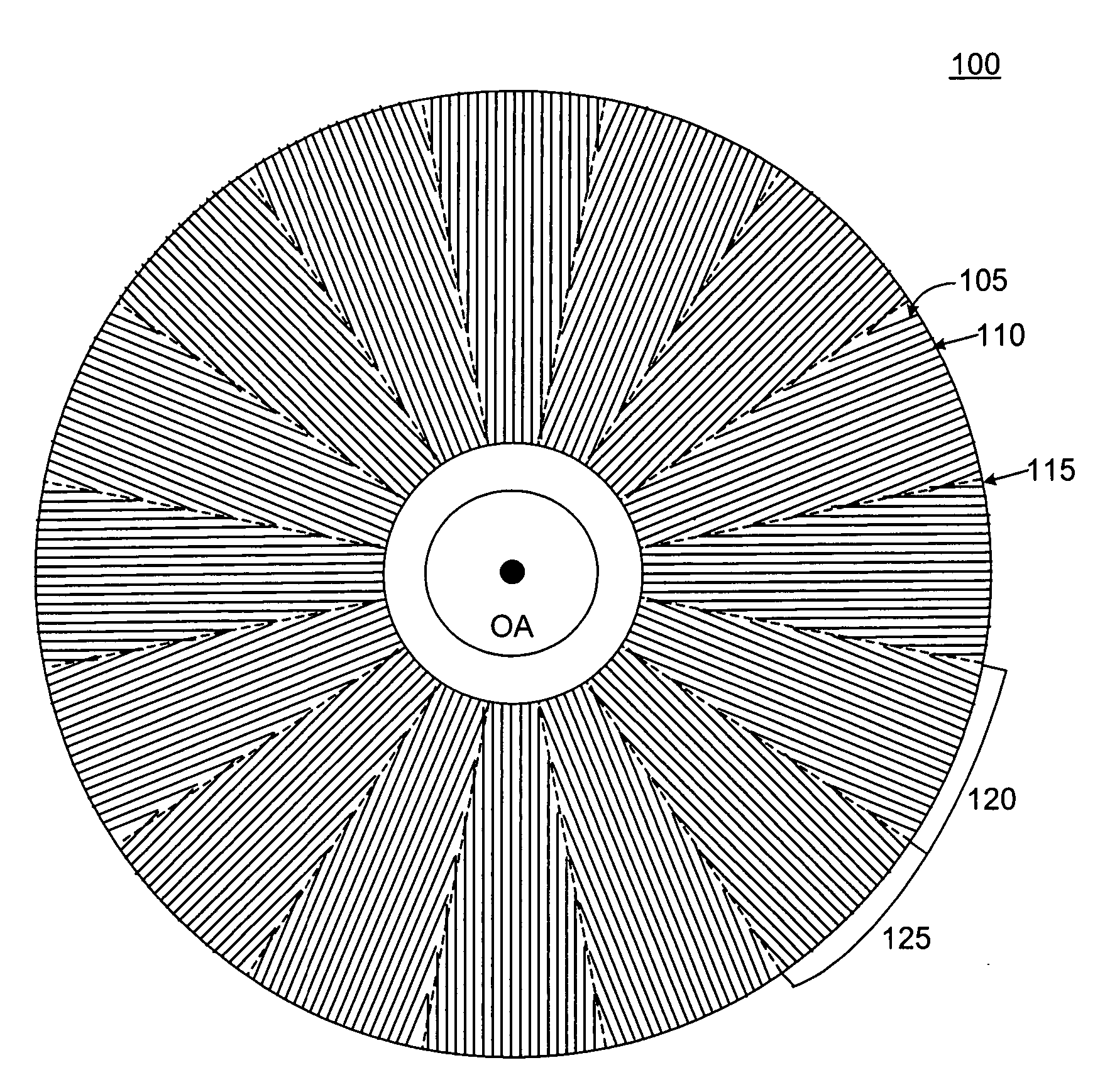
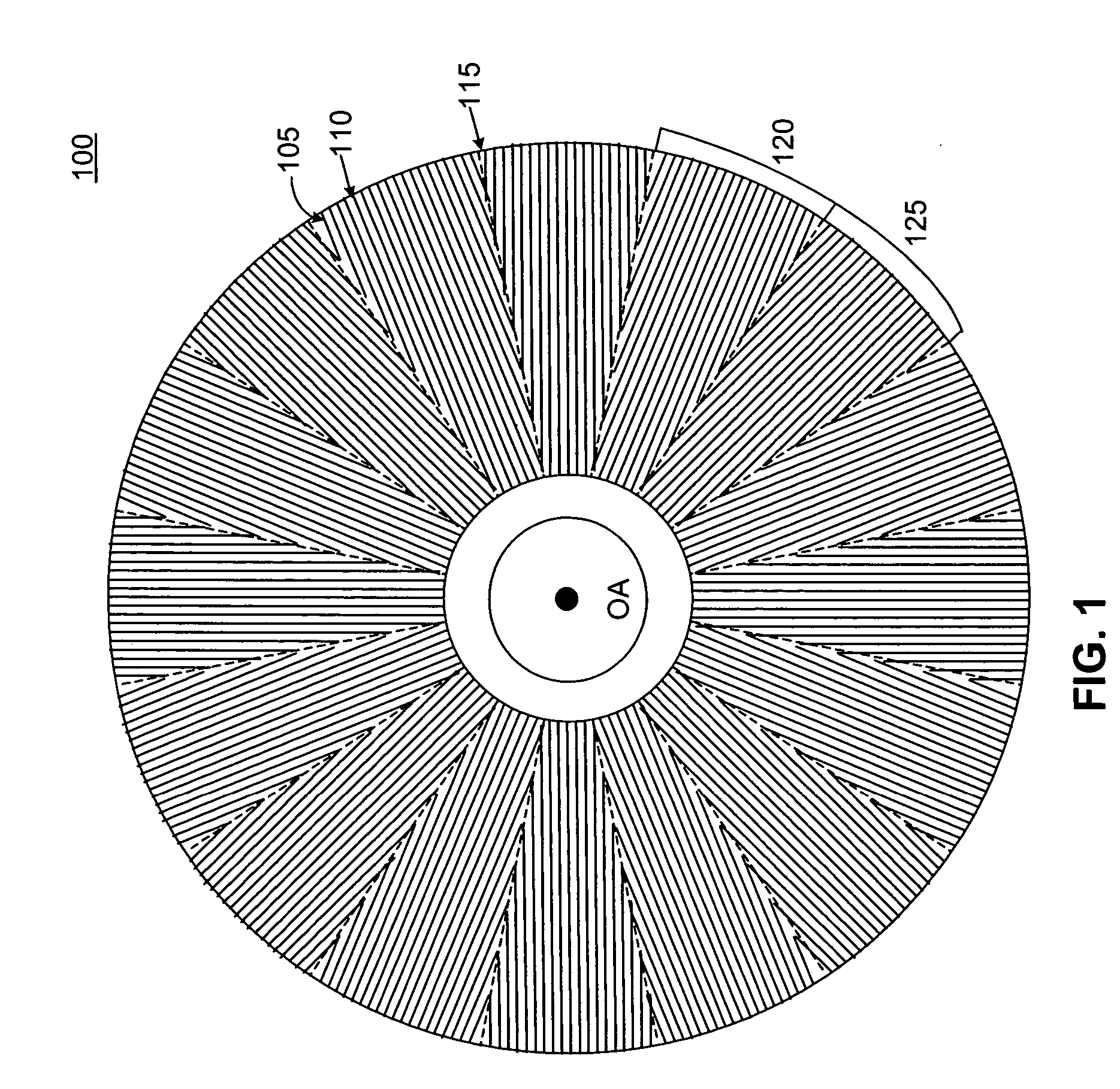
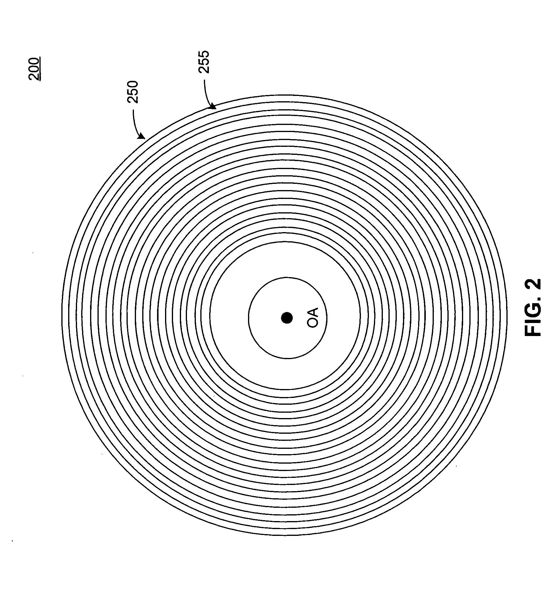
[0022] In one embodiment, a patterned grid polarizer is provided for use in lithography. Such polarizers comprise a substrate that is transparent to ultraviolet (UV) light; and an array of elements patterned on the substrate, wherein the elements polarize UV light.

[0023] Grid Element Patterns

[0024] The present invention provides UV polarizers with elements on the substrate patterned in a variety of ways. In certain aspects of the present invention, the pattern of elements on the substrate dictates the polarization of the light exiting the polarizer.

[0025] In certain applications, having a pattern of polarization in the pupil of the illuminator of an optical system or the projection optics of a lithographic system is advantageou...


PUM


Abstract

The invention relates to a patterned grid polarizer for use in lithography, comprising a substrate that is transparent to ultraviolet (UV) light; and an array of elements patterned on the substrate, wherein the elements polarize UV light. The array of elements can be patterned to produce tangentially or radially polarized UV light.

Description


Claims


Application Information

Patent Timeline
Owner ASML HLDG NV
Learn More