
Method of cleaning a rotary concentrator

Active Publication Date: 2005-10-06
DURR SYST INC
View PDF25 Cites 5 Cited by
  • Summary
  • Abstract
  • Description
  • Claims
  • Application Information

AI Technical Summary

Benefits of technology

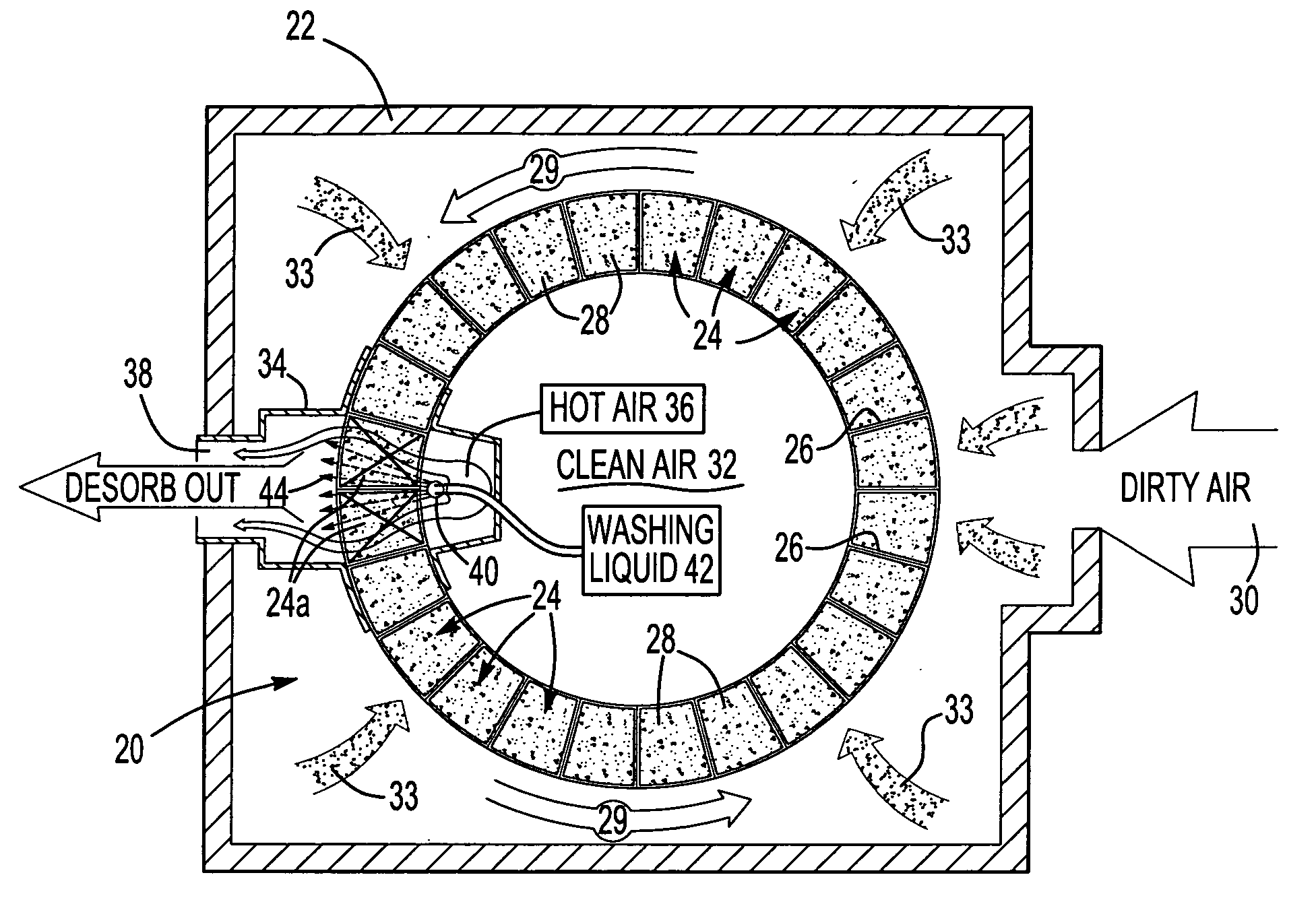
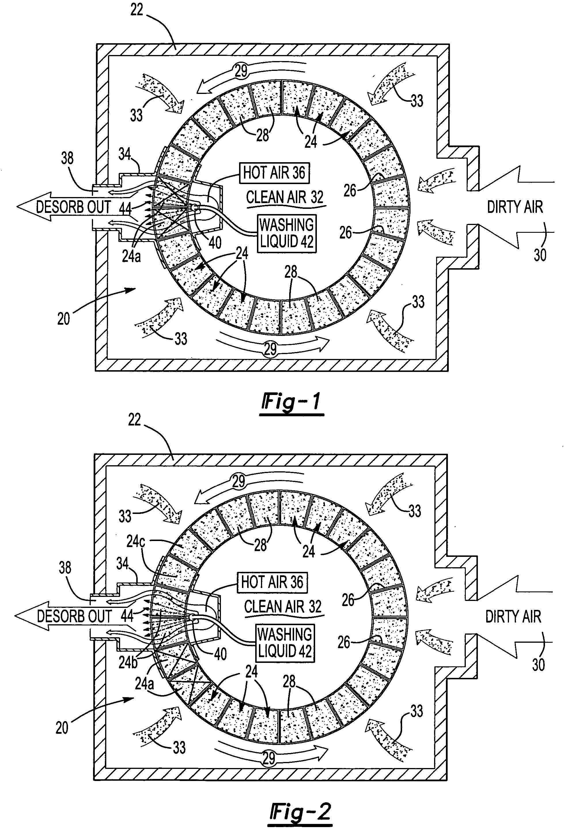
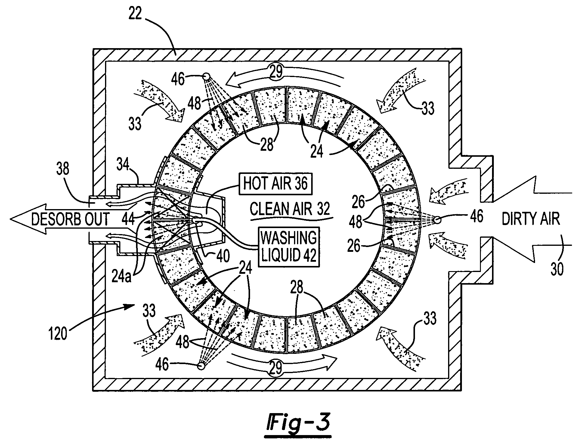
[0004] The method of this invention then includes rotating the rotatable support supporting the sectors of adsorbent media one full revolution or 360 degrees plus at least one desorb sector to bring the adsorbent sector opposite the wash spray nozzle in the desorb supply plenum and the rotatable support is stopped again and the spray or sprays are activated to clean the next adsorbent sector or sectors. The wheel again turns through one full revolution plus at least one desorb sector and this process is repeated until all of the adsorbent media is washed at least once. This intermittent method of washing the adsorbent media of a rotary concentrator does not adversely affect the performance of the concentrator because only one small portion of the adsorbent media is washed at a time while the remaining sectors or sections of the adsorbent media continue to remove and capture the VOCs and SVOCs from the waste stream. The method of in-situ cleaning of the adsorbent media of a rotary concentrator of this invention thus maintains the efficiency of the rotary concentrator while cleaning the adsorbent media of SVOCs.

Problems solved by technology

These compounds tend to accumulate on the adsorbent of the concentrator, rendering it ineffective over a period of time.
As will be understood, this method of cleaning the adsorbent of a rotary concentrator significantly reduces the efficiency of the concentrator requiring the contaminated or waste stream to be stopped or transferred to a second rotary concentrator during the washing cycle.

Method used


Image

  • Method of cleaning a rotary concentrator
  • Method of cleaning a rotary concentrator
  • Method of cleaning a rotary concentrator

Examples


Embodiment Construction

[0009] The method of cleaning in-situ adsorbent media of a rotary concentrator of this invention may be utilized with any conventional rotary concentrator having a plurality of sectors each containing adsorbent media. Thus, the disclosed embodiment of the rotary concentrator is for illustrative purposes only and does not limit the method of this invention except as set forth in the appended claims.

[0010]FIGS. 1 and 2 illustrate one embodiment of a rotary concentrator 20 which is typically enclosed within an enclosure or housing 22. The rotary concentrator 20 includes a plurality of segments or sectors 24, each including a housing 20 enclosing adsorbent media 28. As will be understood, the preferred adsorbent media will depend upon the application of the rotary concentrator, but zeolite is a typical adsorbent media for a rotary concentrator of this type. In a typical application, the sectors 24 are arranged in a circle as shown and the sectors 24 are supported on a rotatable support...


PUM


Abstract

A method of cleaning the adsorbent media of a rotary concentrator in-situ while maintaining operation of the concentrator, including directing washing liquid into the sectors in the desorb plenum, then rotating the sectors one full revolution plus at least one sector into the desorb plenum to bring a second sector into the desorb plenum, washing the second sector and repeating the cycle until all of the adsorbent media is washed. The method may also include directing washing liquid into sectors not located in the desorb plenum.

Description

BACKGROUND OF THE INVENTION [0001] A rotary concentrator is an air pollution abatement device that removes or captures volatile organic compounds (VOCs) from a contaminated air stream or waste stream, thus cleaning the air stream and letting clean gas pass through the concentrator as disclosed, for example, in U.S. Pat. No. 5,693,123 assigned to the assignee of this application. Sometimes, along with the VOCs, semi-volatile compounds (SOVCs), in the form of a liquid organic mist or entrained particulates is also present in the contaminated air stream. These compounds tend to accumulate on the adsorbent of the concentrator, rendering it ineffective over a period of time. At present, the adsorbent in the sections of the rotary concentrator are washed using a suitable liquid, primarily water, which may include a detergent, by shutting down the rotary concentrator and spraying the washing liquid through the adsorbent of the rotary concentrator either in-situ or by removing and cleaning ...

Claims


Application Information

Patent Timeline
IPC IPC(8): B01D53/02B01D53/06B01D53/08
CPCB01D53/06F24F2221/22F24F2203/1052B01D2257/708
Inventor MCANESPIE, DONALD
Owner DURR SYST INC
Learn More