
Electrical device with vents

Inactive Publication Date: 2007-03-08
ASUSTEK COMPUTER INC
View PDF11 Cites 35 Cited by
  • Summary
  • Abstract
  • Description
  • Claims
  • Application Information

AI Technical Summary

Benefits of technology

[0009] It is another objective of the present invention to provide an electrical device with vents that prevents dust while maintaining heat emission efficiency.
[0010] In accordance with the foregoing objectives, the present invention offers a sliding part for a traditional electrical device. When the electrical device is powered off or the electrical device is powered on but has not reached a certain high temperature, the sliding part is at a second position to close the heat emission openings. Thus, the sliding part can prevent the intruding dust that damages the circuitry inside the device case. When the electrical device is powered on and reaches a certain high temperature to emit heat, the sliding part is moved by a pulling mechanism to a first position to open the heat emission openings. Thus, the openings can allow the heat to emit outward. When the temperature inside the case declines or the device is powered off, the sliding part is moved back to the second position by a returning mechanism to close the heat emission openings again.
[0013] By the application of the controllable sliding part of this invention to open and close the heat emission openings, dust intrusion is prevented and heat emission efficiency is maintained. When the electrical device does not reach the heat emission condition, the sliding part closes the heat emission openings to prevent the intruding dust. When the electrical device reaches the heat emission condition, the sliding part is moved to open the heat emission openings to allow the heat to escape. When the temperature of the electrical device declines, the sliding part is moved back to close the heat emission openings again. This invention can prevent the problems associated with the always-open heat emission openings of traditional designs while maintaining the desired heat emission functionality.

Problems solved by technology

These delicate portable devices of high efficiency and small size are plagued by high temperature chips and heat emission inefficacy, which can induce the device functions to fail.
However, dust intrudes the devices through these openings and can make the device functions fail.
The traditional solution of this problem is to install a mask with holes to prevent the intrusive dust, but this solution reduces the efficiency of heat emission.

Method used


Image

  • Electrical device with vents
  • Electrical device with vents
  • Electrical device with vents

Examples


Embodiment Construction

[0018] Reference will now be made in detail to the present preferred embodiments of the invention, examples of which are illustrated in the accompanying drawings. Wherever possible, the same reference numbers are used in the drawings and the description to refer to the same or like parts.

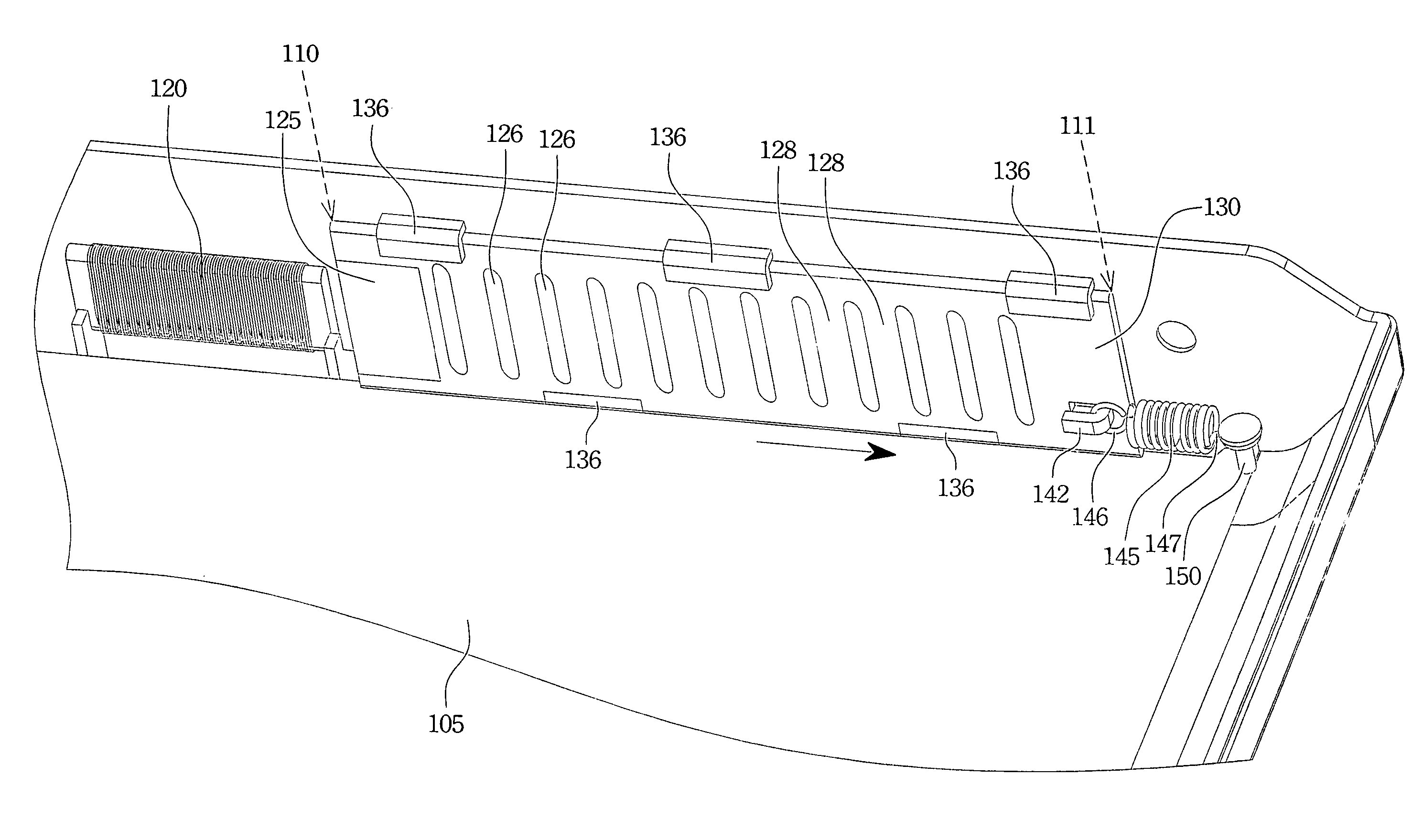
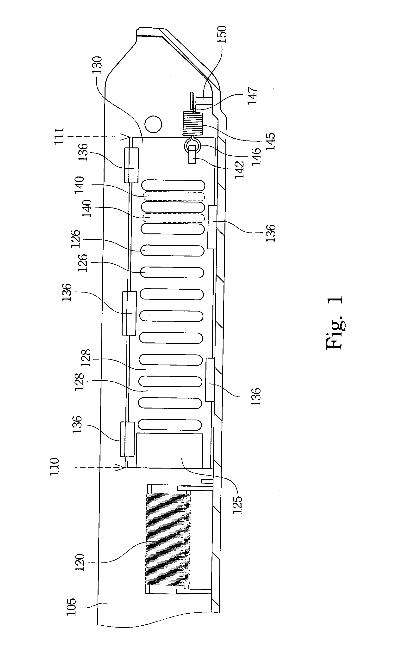
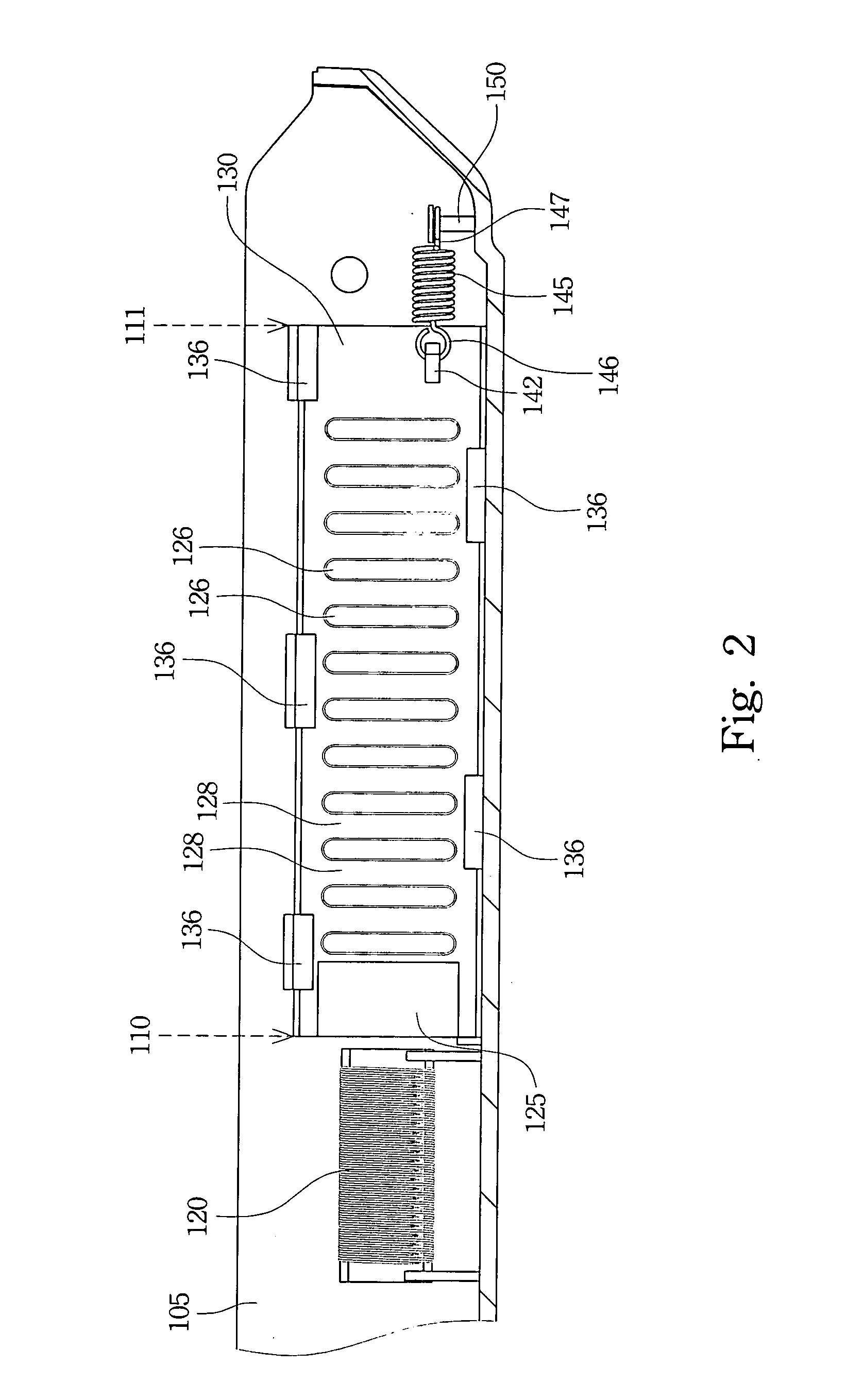
[0019]FIG. 1 is an inner side view of the case according to one preferred embodiment of this invention. There are at least one first vent 140 and a sliding assembly 136 on the case 105. The heat emission openings are constructed from first vents 140. The dotted line indicates that the heat emission openings are closed. The sliding part 130 can slide between a first position and a second position along the sliding assembly 136. When the sliding part 130 is at the first position, the first vent 140 is opened. When the sliding part 130 is at the second position, the first vent 140 is closed. An electromagnetic coil 120 is located at the left side of a first side 110 of the sliding part 130, and there ...


PUM


Abstract

An electrical device with vents is provided. The electrical device comprises a case, a sliding part, a spring, and an electromagnetic coil. The case comprises a first vent and a sliding assembly. The sliding assembly is installed at one side or both sides of the first vent, and the sliding part is movable along the sliding assembly. The spring and the electromagnetic coil are separately on each side of the sliding part. When this electrical device detects that heat should be removed, the electromagnetic coil is powered for generating magnetic force to stretch the spring and move the sliding part to the first position to open the first vents. When the electromagnetic coil is not powered, the spring pulls the sliding part back to the second position to close the first vent.

Description

RELATED APPLICATIONS [0001] The present application is based on, and claims priority from, Taiwan Application Serial Number 94130601, filed Sep. 6, 2005, the disclosure of which is hereby incorporated by reference herein in its entirety. BACKGROUND [0002] 1. Field of Invention [0003] The present invention relates to an electrical device with vents, and especially relates to an electrical device that can open and close the vents by setting conditions automatically. [0004] 2. Description of Related Art [0005] As information technologies and the computer industry develop abundantly, portable devices, such as notebook computers, are becoming sleeker and better miniaturized to keep with modern fashion trends. [0006] These delicate portable devices of high efficiency and small size are plagued by high temperature chips and heat emission inefficacy, which can induce the device functions to fail. Therefore, the design of heat emission mechanisms becomes an important topic. [0007] Nowadays, ...

Claims


Application Information

Patent Timeline
IPC IPC(8): H02B1/56
CPCG06F1/203
Inventor KANG, LUN-WEI
Owner ASUSTEK COMPUTER INC
Learn More