
Catalyst-containing reaction accelerator and steam reforming method using hydrocarbon

a catalyst and reaction accelerator technology, applied in the direction of physical/chemical process catalysts, other chemical processes, separation processes, etc., can solve the problems of reducing the specific surface area, deteriorating the catalytic action, and reducing the performance of solid catalysts after long-term us

Inactive Publication Date: 2005-09-29
KK TOSHIBA
View PDF8 Cites 11 Cited by
  • Summary
  • Abstract
  • Description
  • Claims
  • Application Information

AI Technical Summary

Problems solved by technology

Unfortunately, when the mixture of the solid catalyst and carbon dioxide absorbent is thus filled, the performance of the solid catalyst deteriorates after a long-term use.
Since the solid catalyst is a porous material, its pores are closed by covering with the molten carbonate, thereby reducing the specific surface area and deteriorating the catalytic action.
Especially in a long-term use in which absorption and regeneration are repeated by the carbon dioxide absorbent, the performances of the solid catalyst and absorbent is deteriorated by occurring the movement and outflow of this molten carbonate.
Especially when the gas flow amount is large the carbon dioxide absorbing action of the carbon dioxide absorbent filled in the outer tube does not contribute highly.
This makes it difficult to achieve the effect of shifting the chemical equilibrium toward the hydrogen production side as indicated by formula (3).
Unfortunately, when this carbon dioxide absorbent is filled in the holes of the outer shell so as to mix with a solid catalyst, the molten carbonate and the solid catalyst partially come in contact with each other.
In this absorbent having the above constitute, it is difficult to prevent deterioration of the solid catalyst after a long-term repetitive use.

Method used


Image

  • Catalyst-containing reaction accelerator and steam reforming method using hydrocarbon
  • Catalyst-containing reaction accelerator and steam reforming method using hydrocarbon
  • Catalyst-containing reaction accelerator and steam reforming method using hydrocarbon

Examples


example 1

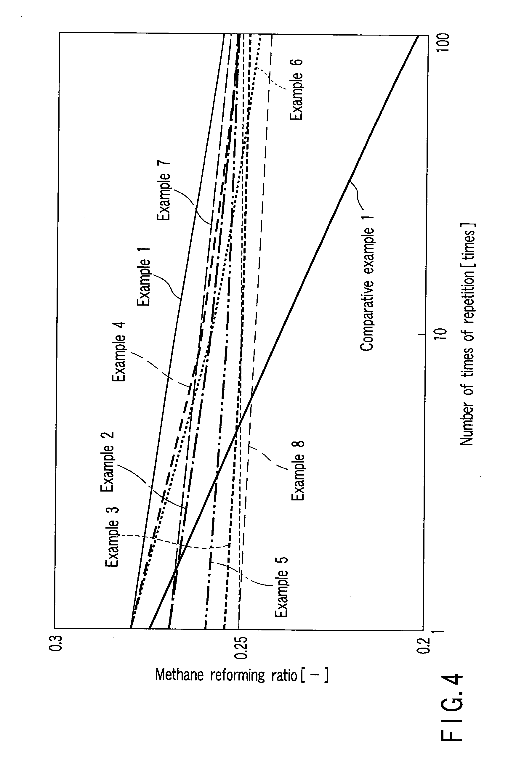
[0065] A silicon dioxide powder having an average particle diameter of 10 μm, a lithium carbonate powder having an average particle diameter of 1 μm, and a potassium carbonate powder having an average particle diameter of 1 μm were so weighed that the molar ratio of silicon dioxide:lithium carbonate:potassium carbonate was 1:2:0.1, thereby obtaining a material powder. Subsequently, 10 wt % of a fibrous lithium titanate powder having an average diameter of 0.5 μm and an average length of 15 μm were added to the material powder. The mixture was milled and mixed by a ball mill. The resultant material powder mixture was heated in a boxy electric oven in the atmosphere at 900° C. for 8 hrs, thereby synthesizing lithium silicate (a composite absorbent material) containing the fibrous lithium titanate. The obtained composite absorbent material was milled by the ball mill such that the lithium silicate had an average particle diameter of 5 μm, and the fibrous lithium titanate had an average...

example 2

[0067] 20 wt % of a fibrous lithium titanate powder having an average diameter of 0.5 μm and an average length of 15 μm were added to a material powder containing a silicon dioxide powder, lithium carbonate powder, and potassium carbonate powder similar to those of Example 1. The mixture was milled and mixed by a ball mill. The resultant material powder mixture was heated in a boxy electric oven at 900° C. for 8 hrs, thereby synthesizing lithium silicate (a composite absorbent material) containing the fibrous lithium titanate. The obtained composite absorbent material was milled by the ball mill such that the lithium silicate had an average particle diameter of 5 μm, and the fibrous lithium titanate had an average length of 10 μn. This composite absorbent material powder was filled in a metal mold having an inner diameter of 5 mm, and molded under pressure to form a columnar composite absorbent. This composite absorbent had a diameter of 5 mm and a length of 8 mm. In addition, the c...

example 3

[0069] 30 wt % of a fibrous lithium titanate powder having an average diameter of 0.5 μm and an average length of 15 μm were added to a material powder containing a silicon dioxide powder, lithium carbonate powder, potassium carbonate powder similar to those of Example 1. The mixture was milled and mixed by a ball mill. The resultant material powder mixture was heated in a boxy electric oven at 900° C. for 8 hrs, thereby synthesizing lithium silicate (a composite absorbent material) containing the fibrous lithium titanate. The obtained composite absorbent material was milled by the ball mill such that the lithium silicate had an average particle diameter of 5 μm, and the fibrous lithium titanate had an average length of 10 μm. This composite absorbent material powder was filled in a metal mold having an inner diameter of 5 mm, and molded under pressure to form a columnar composite absorbent. This composite absorbent had a diameter of 5 mm and a length of 8 mm. In addition, the compo...


PUM

PropertyMeasurementUnit
Temperatureaaaaaaaaaa
Diameteraaaaaaaaaa

Abstract

A catalyst-containing reaction accelerator used in a steam reforming reaction of hydrocarbon comprises a solid catalyst to accelerate the steam reforming reaction, and a composite absorbent which is mixed with the solid catalyst. The composite absorbent has a main absorbent which contains a lithium-containing oxide for absorbing and desorbing carbon dioxide by-produced by the steam reforming reaction, and a molten carbonate holding material which does not react with the main absorbent at a temperature at which the main absorbent absorbs and desorbs carbon dioxide.

Description

CROSS-REFERENCE TO RELATED APPLICATIONS [0001] This application is based upon and claims the benefit of priority from prior Japanese Patent Application No. 2004-096944, filed Mar. 29, 2004, the entire contents of which are incorporated herein by reference. BACKGROUND OF THE INVENTION [0002] 1. Field of the Invention [0003] The present invention relates to a catalyst-containing reaction accelerator which is used in a steam reforming reaction for hydrocarbons and has a catalytic function and a function of absorbing and removing carbon dioxide produced as a by-product, and a steam reforming method using hydrocarbon. [0004] 2. Description of the Related Art [0005] As is well known, a steam reforming method which causes a hydrocarbon such as methane to react with steam at high temperatures produces hydrogen and by-produces carbon dioxide. [0006] Jpn. Pat. Appln. KOKAI Publication No. 10-152302 discloses a method which, in a reaction apparatus for performing the steam reforming reaction d...

Claims


Application Information

Patent Timeline
IPC IPC(8): B01J20/04B01J20/06B01D53/14B01J20/08B01J20/10B01J21/18B01J23/58B01J23/755B01J23/78B01J27/232B01J35/00B01J37/04C01B3/24C01B3/38C01B3/50C01B3/56
CPCB01J20/041B01J20/28004B01J23/755B01J23/78B01J35/0006B01J37/04B01J2220/42C01B3/384C01B3/508C01B2203/0233C01B2203/0425C01B2203/0475C01B2203/1058C01B2203/1241Y02C10/06B01J20/06B01J20/08B01J20/10B01J20/0211B01J23/58Y02P20/52Y02C20/40B01J35/19
Inventor ESSAKI, KENJIKATO, MASAHIROYOSHIKAWA, SAWAKOIMADA, TOSHIHIRO
Owner KK TOSHIBA
Learn More